 Back
BackStudy Notes: Ohm’s Law, Resistors, and DC Circuits
Study Guide - Smart Notes
 Tailored notes based on your materials, expanded with key definitions, examples, and context.
Ohm’s Law and Electrical Resistance
Introduction to Ohm’s Law
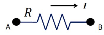
Ohm’s Law is a fundamental principle in physics that describes the relationship between voltage, current, and resistance in an electrical circuit. It is named after Georg Simon Ohm, who first formulated the law in the early 19th century.
Ohm’s Law: The current (I) passing through a conductor between two points is directly proportional to the voltage (V) across the two points and inversely proportional to the resistance (R).
Mathematical Expression:
Resistance: Resistance is the property of a material that opposes the flow of electric current, causing energy dissipation as heat.
Example: If a resistor of 10 Ω is connected across a 5 V battery, the current is A.

Types of Resistors
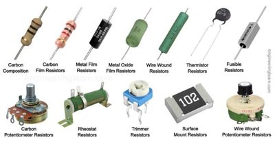
Resistors are components used to control current in circuits. They come in various types, each suited for specific applications.
Carbon Composition, Carbon Film, Metal Film, Metal Oxide Film: Used for general circuit applications.
Wire Wound, Thermistor, Fusible Resistors: Used for high-power or temperature-sensitive applications.
Potentiometer, Rheostat, Trimmer: Adjustable resistors for tuning circuits.
Surface Mount Resistors: Used in compact electronic devices.
Resistors in Series and Parallel
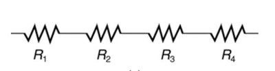
Resistors in Series
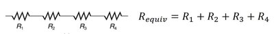
When resistors are connected end-to-end, they are said to be in series. The total resistance is the sum of individual resistances.
Formula:
Current: The same current flows through each resistor.
Voltage: The total voltage is divided among the resistors.
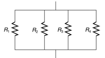
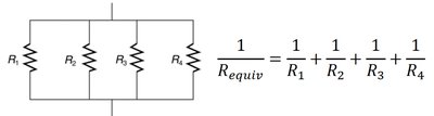
Resistors in Parallel
Resistors are in parallel when connected across the same two points. The equivalent resistance is less than any individual resistor.
Formula:
Voltage: The same voltage is applied across each resistor.
Current: The total current is the sum of the currents through each resistor.
DC Circuits: Series and Parallel Applications
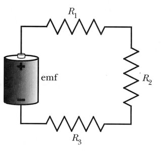
Series Circuit Example
In a series circuit, the current is the same through all components, and the total resistance is the sum of individual resistances.
Example: Three resistors (R1, R2, R3) in series with a battery.
Current Calculation:
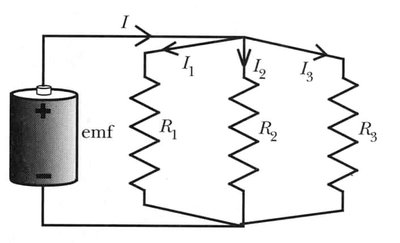
Parallel Circuit Example
In a parallel circuit, the voltage across each branch is the same, and the total current is divided among the branches.
Example: Three resistors (R1, R2, R3) in parallel with a battery.
Current Calculation: , where is calculated using the parallel formula.
Practical Applications: Household Circuits and Safety
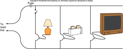
Household Circuits
Household electrical circuits often use parallel wiring to ensure that each device receives the same voltage. Fuses and circuit breakers are used for safety to prevent excessive current.
Fuse: A safety device that melts and breaks the circuit if the current is too high.
Circuit Breaker: A switch that opens the circuit when excessive current is detected.
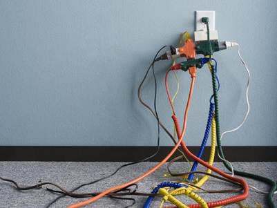
Common Issues: Overloading, short circuits, and ground faults can cause excessive current and trigger safety devices.
Real vs Ideal Batteries
Battery Internal Resistance
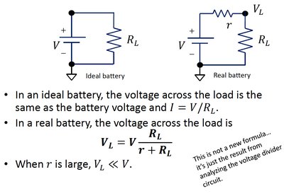
Real batteries have internal resistance, which affects the voltage delivered to the load. As internal resistance increases, the battery's performance decreases.
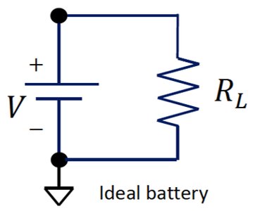
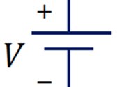
Ideal Battery: Delivers constant voltage regardless of current.
Real Battery: Voltage drops as current increases due to internal resistance.
Formula:
Joule’s Law and Power Dissipation
Joule’s Law
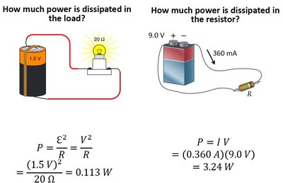
Joule’s Law describes the rate at which electrical energy is converted into heat in a resistor.
Formula:
Application: Used to calculate power dissipation in resistors and electrical devices.
Summary Table: Series vs Parallel Resistors
Connection Type | Formula for Equivalent Resistance | Current | Voltage |
|---|---|---|---|
Series | Same through all | Divided among resistors | |
Parallel | Divided among branches | Same across all |
Key Points for Exam Preparation
Understand and apply Ohm’s Law in circuit analysis.
Calculate equivalent resistance for series and parallel circuits.
Recognize the effects of internal resistance in real batteries.
Apply Joule’s Law to determine power dissipation.
Identify safety devices in household circuits and their function.
Additional info: The notes expand on brief points with academic context, including definitions, formulas, and practical examples for self-contained study.
