 Back
BackThe Wave Nature of Light – Study Notes (Giancoli, Chapter 24)
Study Guide - Smart Notes
 Tailored notes based on your materials, expanded with key definitions, examples, and context.
The Wave Nature of Light
Waves Versus Particles; Huygens’ Principle and Diffraction
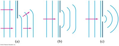
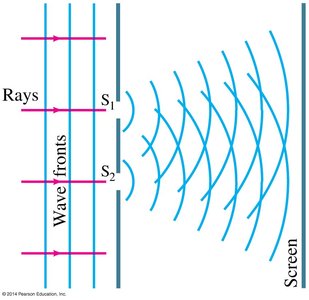
The nature of light has been debated for centuries, with early theories proposing both wave-like and particle-like behavior. The wave theory of light is supported by phenomena such as interference and diffraction, which cannot be explained by particle theory alone. Huygens’ Principle states that every point on a wavefront acts as a source of secondary spherical wavelets, and the new wavefront is the tangent to these wavelets. This principle explains how waves propagate and bend around obstacles, a phenomenon known as diffraction.
Diffraction is the bending of waves around obstacles and openings, demonstrating the wave nature of light.
Huygens’ Principle provides a geometric construction for predicting the future position of a wavefront.
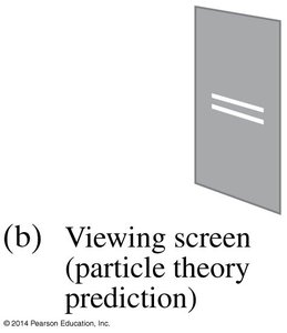
Particle theory cannot account for diffraction patterns observed with light.
Huygens’ Principle and the Law of Refraction
Huygens’ Principle also explains the law of refraction (Snell’s Law). When a wavefront passes from one medium to another, the speed of light changes, causing the wavefront to bend. The frequency of light remains constant, but the wavelength changes according to the refractive indices of the two media:
As light enters a medium with a higher index of refraction, its speed decreases and the wavelength shortens.
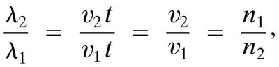
The relationship between the wavelengths and indices of refraction is given by:
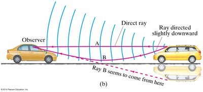
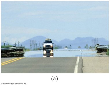
Highway mirages are an example of refraction due to a gradient in the index of refraction in heated air.
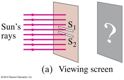
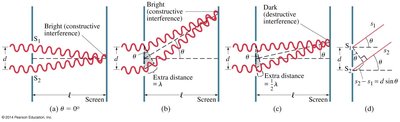
Interference—Young’s Double-Slit Experiment
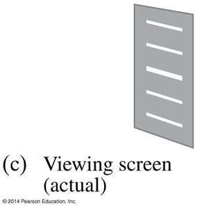
Interference is a hallmark of wave behavior. In Young’s double-slit experiment, light passing through two closely spaced slits produces an interference pattern of bright and dark fringes on a screen. This occurs because the light waves from each slit combine constructively (bright) or destructively (dark) depending on their path length difference.
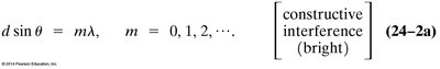
Constructive interference (bright fringes) occurs when the path difference is an integer multiple of the wavelength.
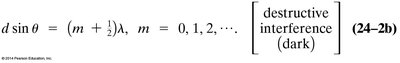
Destructive interference (dark fringes) occurs when the path difference is a half-integer multiple of the wavelength.
The conditions for constructive and destructive interference are:
The intensity pattern shows alternating bright and dark fringes, with the central maximum being the brightest.
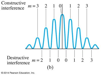
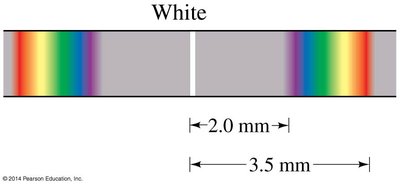
For white light, the position of the maxima depends on wavelength, resulting in colored fringes.
The Visible Spectrum and Dispersion
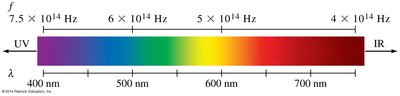
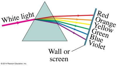
The visible spectrum of light ranges from approximately 400 nm (violet) to 750 nm (red). Light with shorter wavelengths is ultraviolet, while longer wavelengths are infrared. The index of refraction of a material varies with wavelength, causing dispersion—the separation of light into its component colors.
Dispersion explains why a prism splits white light into a rainbow of colors.
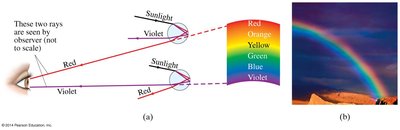
Atmospheric rainbows are formed by dispersion in water droplets.
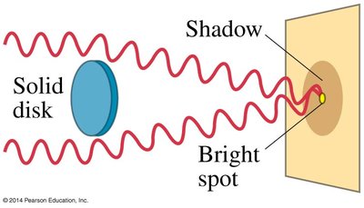
Diffraction by a Single Slit or Disk
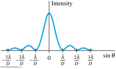
Light also exhibits diffraction when passing through a single slit or around a disk. The resulting diffraction pattern consists of a central bright maximum and alternating dark and bright fringes. This pattern arises from the interference of wavelets originating from different points across the slit width.
The minima of the single-slit diffraction pattern occur when:
Where D is the slit width, θ is the angle, and m is the order of the minimum.
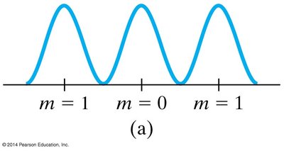
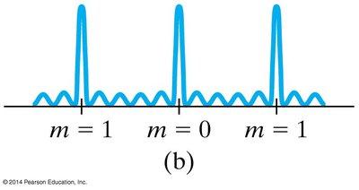
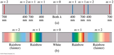
Diffraction Grating
A diffraction grating consists of many equally spaced slits or lines. When light passes through or reflects from a grating, it produces sharp, narrow maxima at specific angles, determined by the grating equation. The more lines per unit length, the narrower and more widely separated the maxima.
The condition for constructive interference (maxima) is:
Where d is the distance between adjacent slits, θ is the angle, m is the order, and λ is the wavelength.
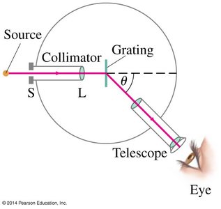
The Spectrometer and Spectroscopy
A spectrometer is an instrument used to measure the wavelengths of light with high accuracy, often using a diffraction grating or prism. Spectroscopy allows for the identification of atoms and molecules by their characteristic emission or absorption lines.
The wavelength can be determined by measuring the angle of diffraction:
Each element has a unique spectral fingerprint, useful in chemical analysis and astronomy.
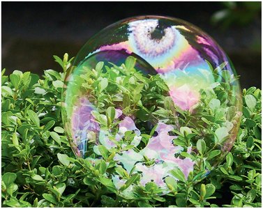
Interference in Thin Films
Interference can also occur in thin films, such as soap bubbles or oil slicks. Light reflects from both the top and bottom surfaces of the film, and the path length difference leads to constructive or destructive interference, producing colorful patterns.
The observed colors depend on the film thickness, the wavelength of light, and the angle of incidence.
Thin-film interference is responsible for the iridescent colors seen in soap bubbles.
Summary Table: Key Equations and Concepts
Concept | Equation | Description |
|---|---|---|
Wavelength in medium | Wavelength changes with refractive index | |
Double-slit constructive interference | Bright fringes (m = 0, 1, 2, ...) | |
Double-slit destructive interference | Dark fringes (m = 0, 1, 2, ...) | |
Single-slit diffraction minima | Minima (m = ±1, ±2, ...) | |
Diffraction grating maxima | Sharp maxima for many slits | |
Wavelength measurement (spectrometer) | Determining wavelength from grating |
Additional info:
Coherent sources are required for stable interference patterns; they must have the same frequency and a constant phase relationship.
Dispersion is responsible for many natural phenomena, such as rainbows and the splitting of light in prisms.
Thin-film interference is widely used in optical coatings and anti-reflective surfaces.
