 Back
BackVectors: Representation, Addition, and Components
Study Guide - Smart Notes
 Tailored notes based on your materials, expanded with key definitions, examples, and context.
Vectors in Physics
Definition and Representation
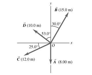
Vectors are fundamental quantities in physics that possess both magnitude and direction. They are used to represent physical quantities such as displacement, velocity, force, and acceleration. Vectors are typically depicted as arrows, where the length of the arrow corresponds to the magnitude and the direction of the arrow indicates the direction of the vector.
Magnitude: The length of the vector, representing the size of the physical quantity.
Direction: The orientation of the vector in space, often specified by an angle relative to a reference axis.
Notation: Vectors are denoted by boldface letters or letters with an arrow above (e.g., \vec{A}).
Vector Components
Any vector in a plane can be resolved into two perpendicular components, usually along the x and y axes. The process of breaking a vector into its components is essential for performing vector addition and other operations.
x-component:
y-component:
Where is the magnitude and is the angle with respect to the x-axis.
Vector Addition
Graphical Method: Head-to-Tail
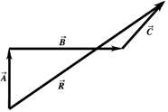
Vectors can be added graphically using the head-to-tail method. The resultant vector is drawn from the tail of the first vector to the head of the last vector. This method visually demonstrates how vectors combine in space.
Resultant Vector (\vec{R}): The sum of two or more vectors.
Procedure: Place the tail of the second vector at the head of the first, and continue for additional vectors. The resultant is drawn from the tail of the first to the head of the last.
Analytical Method: Component Addition
Vectors can also be added analytically by summing their respective components. This method is particularly useful for calculations and is based on the following equations:
Resultant x-component:
Resultant y-component:
Resultant magnitude:
Resultant direction:
Applications: Forces as Vectors
Force Vector Diagrams
Forces are vector quantities and can be represented in diagrams similar to displacement vectors. The direction and magnitude of each force are crucial for determining the net force acting on an object.
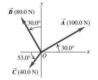
Example: Three forces acting at a point, each with a specified magnitude and direction.
To find the net force, resolve each force into components and sum them.
Example Calculation
Suppose three forces are applied at a point:
\vec{A}: 100.0 N at 30.0° above the x-axis
\vec{B}: 80.0 N at 30.0° above the negative y-axis
\vec{C}: 40.0 N at 53.0° below the negative x-axis
Resolve each force into x and y components, sum the components, and calculate the resultant force using the formulas above.
Summary Table: Vector Properties and Operations
Property | Description |
|---|---|
Magnitude | Length of the vector |
Direction | Angle relative to reference axis |
Components | Projection onto x and y axes |
Addition | Sum of vectors (graphical or analytical) |
Resultant | Combined effect of multiple vectors |
Additional info: The diagrams provided reinforce the concepts of vector representation, vector addition, and the application of vectors to forces, which are foundational topics in Chapter 1: Units, Physical Quantities & Vectors.
