 Back
Wave Optics: Diffraction and Interference
Study Guide - Smart Notes
 Tailored notes based on your materials, expanded with key definitions, examples, and context.
Wave Optics
Introduction to the Wave Model of Light
The wave model of light explains phenomena such as interference and diffraction, which cannot be described by the ray model. In this chapter, we explore how light behaves as a wave, leading to patterns of bright and dark fringes when it passes through slits or gratings.
Diffraction Grating
Principles of Diffraction Grating
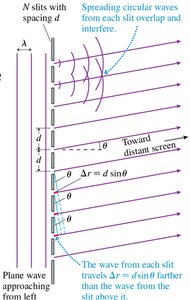
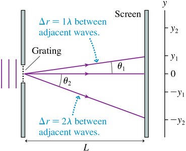
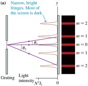
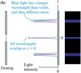
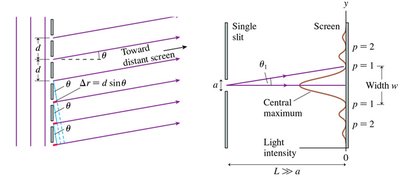
A diffraction grating consists of N closely spaced slits. When light passes through these slits, each acts as a source of diffracted waves, which interfere to produce bright fringes at specific angles. The condition for constructive interference (bright fringes) is:
Order of diffraction (m): Integer values (0, 1, 2, ...)
Angle for bright fringes:
Position on screen:
The intensity of the bright fringes is proportional to the square of the number of slits:
Applications: Diffraction gratings are used in spectroscopy, astronomy, chemical analysis, optical telecommunications, laser wavelength selection, and monochromators.
Reflection Gratings and Natural Examples
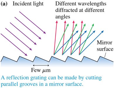
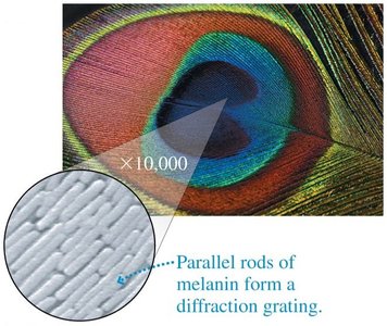
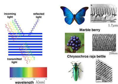
Most practical diffraction gratings are reflection gratings, created by cutting parallel grooves in a mirror surface. The interference pattern is similar to that of transmitted gratings. Naturally occurring reflection gratings, such as those found in peacock feathers, produce structural colors due to periodic microstructures.
Single-Slit Diffraction
Huygens’ Principle and Diffraction
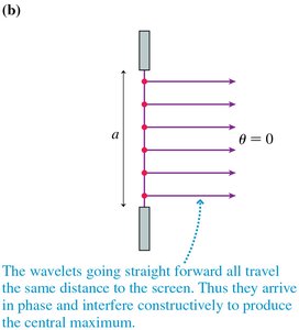
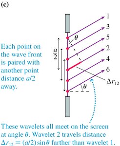
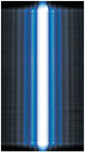
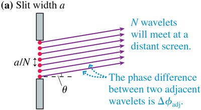
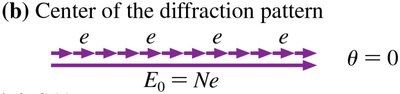
According to Huygens’ principle, every point on a wave front acts as a source of spherical wavelets. When light passes through a single slit, these wavelets interfere to produce a diffraction pattern. The central maximum is formed by wavelets traveling the same distance and arriving in phase.
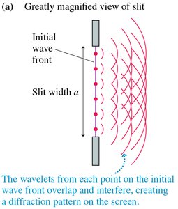
Single-Slit Diffraction Pattern
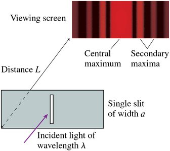
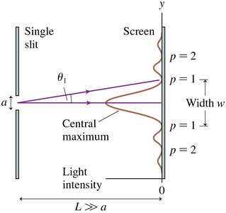
The pattern consists of a bright central maximum and weaker secondary maxima. The dark fringes occur at angles where destructive interference happens:
Condition for dark fringes: , where m = ±1, ±2, ...
Width of central maximum:
Advanced Analysis: Phasor Diagrams and Superposition
Phasor Diagrams in Double-Slit and Single-Slit Diffraction
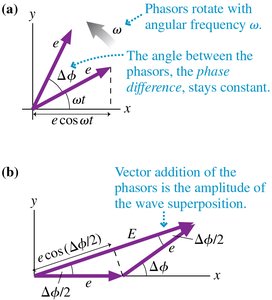
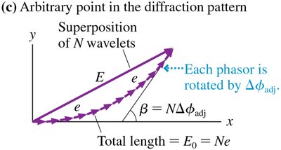
Phasor diagrams are used to visualize the addition of electric field vectors from multiple sources. The amplitude of the superposition is determined by vector addition, and the intensity is proportional to the square of the amplitude.
Double-slit phasor addition:
Single-slit phasor addition: For N wavelets, the total amplitude is the arc of a circle subtended by angle β.
Intensity formula:
N-Slit Interference and Diffraction Envelope
Geometric Field Sum and Intensity
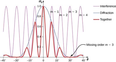
For N slits, the path and phase difference between adjacent slits determines the interference pattern. The observed pattern is a product of the single-slit diffraction envelope and the N-slit interference factor:
Path difference:
Phase difference:
Intensity:
Where ,
The envelope limits the heights of the narrow principal maxima.
Principal Maxima, Minima, and Missing Orders
Principal maxima:
Intensity at maxima:
Interference minima:
Envelope zeros:
Missing orders: Occur when an interference maximum coincides with an envelope zero.
Circular-Aperture Diffraction
Diffraction Through Circular Apertures
When light passes through a circular aperture, the diffraction pattern consists of a central bright spot surrounded by rings. The angle of the first minimum is:
Width of central maximum:
Wave vs. Ray Model of Light
When to Use Each Model
If the spreading due to diffraction is less than the size of the opening, the ray model is appropriate. If the spreading is greater, the wave model must be used. The crossover occurs when the central maximum width equals the opening size:
Interferometers
Michelson Interferometer
An interferometer uses interference to make precise measurements. The Michelson interferometer splits a beam into two paths, recombines them, and observes interference based on path-length differences. Applications include displacement measurement, wavelength determination, refractive index measurement, spectroscopy, optical testing, fundamental physics experiments, and gravitational-wave detection.
Path-length difference:
Number of maxima:
Holography
Recording and Reconstruction
Holography records the interference pattern of light scattered from an object and a reference beam. When the reference beam is sent through the hologram, it reconstructs the original wave front, producing a three-dimensional image.
Summary Table: Diffraction and Interference Formulas
Phenomenon | Condition | Formula |
|---|---|---|
Diffraction Grating | Bright fringes | |
Single-Slit Diffraction | Dark fringes | |
Circular Aperture | First minimum | |
Michelson Interferometer | Maxima count |
