 Back
BackWave Optics: Diffraction and Interference of Light
Study Guide - Smart Notes
 Tailored notes based on your materials, expanded with key definitions, examples, and context.
Diffraction and Interference of Light
Diffraction of Waves
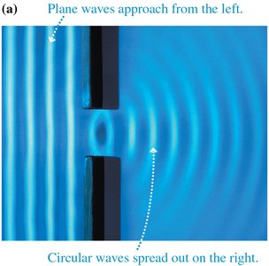
Diffraction is a fundamental property of waves, describing how they spread out after passing through an opening or around an obstacle. This effect is observable in water waves, sound waves, and light waves, though the degree of spreading depends on the wavelength and the size of the opening.
Definition: Diffraction is the spreading of waves as they pass through an aperture or around an obstacle.
Key Point: The amount of diffraction increases as the size of the opening approaches the wavelength of the wave.
Example: Water waves passing through a narrow gap spread out in circular patterns behind the opening.
Models of Light
Light can be described using three main models, each applicable in different contexts:
Wave Model: Light behaves as a wave, exhibiting phenomena such as diffraction and interference. This model is central to wave optics.
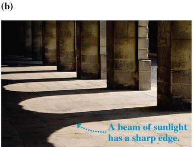
Ray Model: Light travels in straight lines, forming sharp shadows and explaining reflection and refraction. This is the basis of ray optics.
Photon Model: In quantum theory, light consists of photons, which exhibit both wave-like and particle-like properties.
Application: The wave model explains why light diffracts when passing through small openings, while the ray model is used for larger apertures where diffraction is negligible.
Diffraction of Light
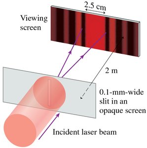
Light waves, due to their short wavelength, only exhibit noticeable diffraction when passing through very small openings. For example, red light passing through a 0.1 mm wide slit spreads out, demonstrating diffraction.
Key Point: Diffraction is observable for light when the aperture width is comparable to the wavelength (hundreds of nanometers).
Example: Laser light passing through a narrow slit produces a diffraction pattern on a screen.
Interference: Double-Slit Experiment
Young’s Double-Slit Experiment
Young’s double-slit experiment demonstrates the wave nature of light by producing an interference pattern of bright and dark fringes on a screen. This occurs when light passes through two closely spaced slits and the waves overlap.
Constructive Interference: Occurs where the path difference between the two waves is an integer multiple of the wavelength, resulting in bright fringes.
Destructive Interference: Occurs where the path difference is a half-integer multiple of the wavelength, resulting in dark fringes.
Equation for Bright Fringes: where
Position of Bright Fringes:


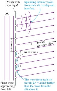
Analyzing Double-Slit Interference
The double-slit interference pattern can be analyzed by considering the path-length difference between the two slits. Constructive interference occurs at angles where the path difference equals an integer multiple of the wavelength.
Path-Length Difference:
Small-Angle Approximation: For small angles, (in radians).
Fringe Spacing:

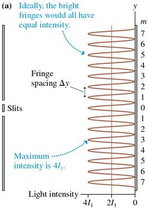
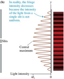
Intensity of the Double-Slit Interference Pattern
The intensity of the double-slit interference pattern varies with position on the screen. Ideally, all bright fringes have equal intensity, but in practice, intensity decreases away from the central maximum due to the finite width of the slits.
Intensity Equation:
Realistic Pattern: The intensity envelope is modulated by single-slit diffraction.
Diffraction Gratings
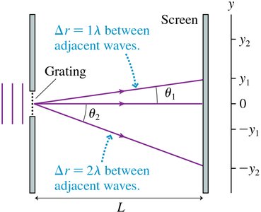
Principles of Diffraction Gratings
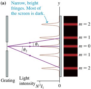
A diffraction grating consists of many closely spaced slits, producing very sharp and bright interference fringes. Each slit acts as a source of diffracted light, and constructive interference occurs at specific angles.
Equation for Bright Fringes:
Order of Diffraction: The integer denotes the order of the fringe.
Intensity: where is the number of slits.
Application: Diffraction gratings are used to measure wavelengths of light with high precision.
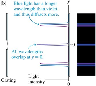
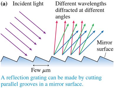
Reflection Gratings
Reflection gratings are manufactured by cutting parallel grooves into a mirror surface. They produce interference patterns similar to transmission gratings and are used in spectroscopy and other applications.
Key Point: Different wavelengths are diffracted at different angles, allowing separation of colors.
Example: Natural reflection gratings, such as peacock feathers, produce vivid colors.
Single-Slit Diffraction
Principles of Single-Slit Diffraction
Single-slit diffraction occurs when light passes through a narrow slit, producing a central bright maximum and weaker secondary maxima. The pattern is explained by Huygens’ principle, which states that each point on a wave front acts as a source of spherical wavelets.
Dark Fringes: Occur at angles where ,
Width of Central Maximum:
Key Point: The narrower the slit, the wider the diffraction pattern.
Circular-Aperture Diffraction
Diffraction Through Circular Openings
When light passes through a circular aperture, the diffraction pattern consists of a central bright spot surrounded by rings. The angle of the first minimum is given by:
Angle of First Minimum:
Width of Central Maximum:
Wave and Ray Models of Light
Choosing the Appropriate Model
The choice between the wave and ray models depends on the size of the aperture relative to the wavelength:
Wave Model: Use when the aperture is smaller than 1 mm; diffraction effects are significant.
Ray Model: Use when the aperture is larger than 1 mm; light travels in straight lines.
Crossover Point:
Interferometers
Michelson Interferometer
An interferometer divides a wave, lets the two parts travel different paths, and then recombines them to produce interference. The Michelson interferometer is used for precise measurements of wavelength.
Constructive Interference: Occurs when the path difference is an integer multiple of the wavelength.
Number of Maxima:
Holography
Recording and Reconstructing Holograms
Holography uses interference and diffraction to record three-dimensional images. A hologram is created by recording the interference pattern between a reference beam and a scattered beam from an object. When illuminated, the hologram reconstructs the original wave front, producing a 3D image.
Key Point: The view is three-dimensional because different portions of the wave front are visible from different angles.
Summary of Key Equations
Double-Slit Bright Fringes:
Double-Slit Fringe Position:
Single-Slit Dark Fringes:
Width of Single-Slit Central Maximum:
Circular Aperture First Minimum:
Michelson Interferometer Maxima:
