 Back
BackWave Optics: Interference, Diffraction, and Applications
Study Guide - Smart Notes
 Tailored notes based on your materials, expanded with key definitions, examples, and context.
Wave Optics
The Wave Model of Light
Light is described as an electromagnetic wave, consisting of oscillating electric and magnetic fields that propagate through space. Unlike mechanical waves, electromagnetic waves can travel through a vacuum as well as through materials. The speed of light in a vacuum is a fundamental constant, denoted as c, with a value of m/s.
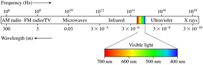
Electromagnetic Spectrum: The electromagnetic spectrum encompasses all types of electromagnetic radiation, which differ only in wavelength and frequency. The visible region ranges from approximately 400 nm (violet) to 700 nm (red).
White Light: White light is a mixture of all visible wavelengths.
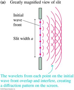
Huygens’ Principle
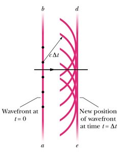
Huygens’ principle states that every point on a wavefront acts as a source of secondary spherical wavelets. The new position of the wavefront after a time interval is the surface tangent to these secondary wavelets. This principle explains the propagation and bending of waves.
Wavefront: A surface over which the phase of the wave is constant.
Secondary Wavelets: Small, spherical waves that spread out from each point on the wavefront.
Interference of Light
Young’s Double-Slit Experiment
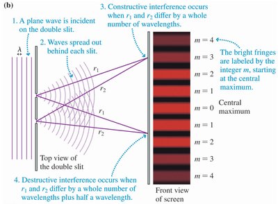
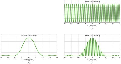
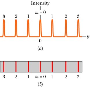
Young’s double-slit experiment demonstrates the wave nature of light through the phenomenon of interference. When coherent light passes through two closely spaced slits, the resulting waves overlap and interfere, producing a pattern of bright and dark fringes on a screen.
Constructive Interference: Occurs when the path difference between the two waves is an integer multiple of the wavelength, resulting in bright fringes.
Destructive Interference: Occurs when the path difference is an odd multiple of half-wavelengths, resulting in dark fringes.
Path Difference:
Conditions:
Bright fringes: , for
Dark fringes: , for
Mathematical Analysis of Double-Slit Interference
For small angles, , where is the position of the m-th bright fringe and is the distance from the slits to the screen.
Fringe Position:
Fringe Spacing:
Wavelength Calculation Example: If mm, mm, cm, then nm.

Coherence
Coherence refers to the property of two waves to maintain a constant phase relationship over time. Only coherent sources produce stable interference patterns. Lasers and light diffracted from a single slit are common sources of coherent light.
Incoherent Sources: Such as candles, do not produce observable interference patterns due to random phase variations.
Thin-Film Interference
Principle and Conditions
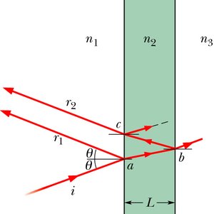
Thin-film interference occurs when light reflects off the upper and lower boundaries of a thin film, causing the reflected waves to interfere. The effect depends on the film’s thickness, the wavelength of light, and the refractive indices of the materials involved.
Index of Refraction: , where is the speed of light in the medium.
Phase Shift: Reflection from a medium of higher refractive index introduces a phase shift of half a wavelength ().
Path Length Difference: , where is the film thickness.
Wavelength in Film:
Constructive Interference (maxima):
Destructive Interference (minima):
Example: Anti-Reflective Coating
Given: Glass (), coating (), air (), nm.
Minimum thickness for destructive interference: nm.
Diffraction
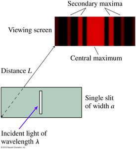
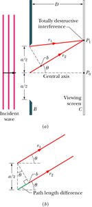
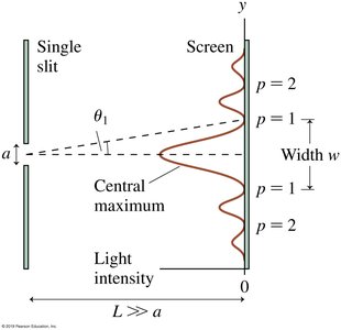
Single-Slit Diffraction
When light passes through a single narrow slit, it spreads out and forms a diffraction pattern on a screen. This pattern consists of a central bright maximum and alternating dark and bright fringes.
Huygens’ Principle: Each point within the slit acts as a source of secondary wavelets that interfere with each other.
Condition for Minima (Dark Fringes): , for
Position of Minima:
Width of Central Maximum:
Effect of Slit Width: Narrower slits produce wider diffraction patterns.
Comparison: Single-Slit vs. Double-Slit Diffraction
Double-slit patterns show sharp interference fringes, while single-slit patterns display a broad central maximum. In double-slit experiments, the interference fringes are modulated by the single-slit diffraction envelope.
Diffraction Gratings
Principle and Applications
A diffraction grating consists of many closely spaced slits. When monochromatic light passes through, it produces a series of sharp, bright lines at specific angles. Diffraction gratings are used to measure wavelengths of light from various sources.
Grating Equation: , where is the grating spacing and is the order of the maximum.
Position of Bright Lines:
Note: For gratings, is not necessarily small, so the small angle approximation may not apply.
Example: Finding Slit Width from Diffraction Pattern
Given: Distance between first and fifth minima mm, cm, nm.
Slit width: mm.
Angle of first minimum: .
