 Back
BackWave Optics: Interference, Diffraction, and Polarization
Study Guide - Smart Notes
 Tailored notes based on your materials, expanded with key definitions, examples, and context.
Wave Optics
Introduction to Wave Optics
Wave optics, also known as physical optics, deals with the study of various phenomena such as interference, diffraction, and polarization, which arise due to the wave nature of light. These phenomena cannot be explained by ray optics and require the consideration of light as a wave.
Interference
Principle of Superposition and Interference
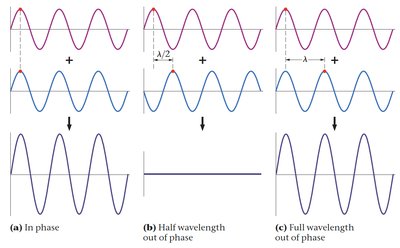
When two or more waves overlap in space, their amplitudes combine according to the principle of superposition. The resulting effect is called interference. Interference can be constructive or destructive depending on the phase relationship between the waves.
Constructive Interference: Occurs when waves are in phase, resulting in a larger amplitude.
Destructive Interference: Occurs when waves are out of phase by half a wavelength, resulting in cancellation (zero amplitude if amplitudes are equal).
Coherent and Monochromatic Sources
Coherent sources: Emit waves with a constant phase difference and the same frequency.
Monochromatic source: Emits light of a single wavelength (or frequency or color).
A coherent source is always monochromatic, but a monochromatic source may not be coherent.
For stable interference patterns, the sources must be both coherent and monochromatic.
Conditions for Interference
Sources must be coherent (constant phase difference).
Sources must be monochromatic (single wavelength).
Young’s Double Slit Experiment
Experimental Setup and Observations
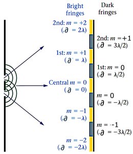
Thomas Young's double slit experiment demonstrated the wave nature of light by producing an interference pattern of bright and dark fringes on a screen. Monochromatic light passes through two closely spaced slits, each acting as a source of coherent waves. The resulting pattern is due to constructive and destructive interference.
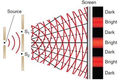
Bright fringes (constructive interference) occur where the path difference is an integer multiple of the wavelength.
Dark fringes (destructive interference) occur where the path difference is an odd multiple of half the wavelength.
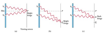
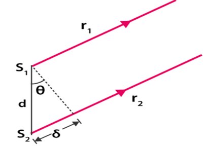
Path Difference and Fringe Formation
The path difference (\( \delta \)) between the two waves arriving at a point on the screen is given by:
For constructive interference (bright fringes):
For destructive interference (dark fringes):
Fringe Location and Spacing
The position \( y \) of the fringes on the screen (distance from the central maximum) is given by:
Fringe spacing increases with wavelength (\( \lambda \)) and screen distance (\( L \)), and decreases with slit separation (\( d \)).
Increasing slit width increases brightness but does not affect fringe spacing.
Effect of Changing Parameters
Increasing slit separation (\( d \)) decreases fringe spacing.
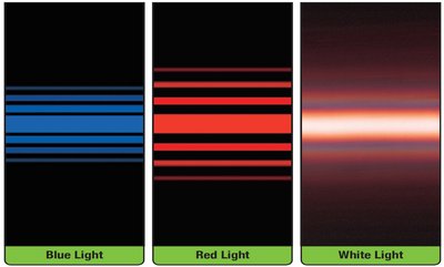
Switching from red to blue light (decreasing \( \lambda \)) decreases fringe spacing.
Replacing monochromatic light with white light produces colored fringes due to superposition of patterns for each wavelength.
Single Slit Diffraction
Diffraction Phenomenon
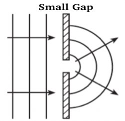
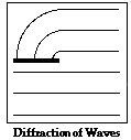
Diffraction is the bending of waves around the corners of an obstacle or through a gap into the region of geometrical shadow. The effect is more pronounced when the slit width is comparable to the wavelength of the light.
Wavelength does not change during diffraction.
Diffraction decreases as the gap becomes larger compared to the wavelength.
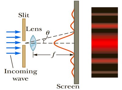
Single Slit Diffraction Pattern
When monochromatic light passes through a single slit, a broad central bright fringe is observed, flanked by weaker bright and dark fringes. The intensity decreases away from the center.
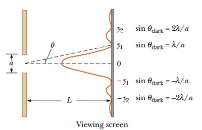
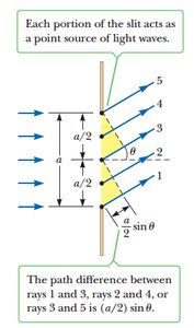
The condition for destructive interference (dark fringes) is:
The width of the central bright fringe is:
Increasing wavelength or screen distance increases the width of the central maximum.
Increasing slit width decreases the width of the central maximum.
Diffraction Grating
Principle and Applications
A diffraction grating consists of many closely spaced slits, producing a pattern similar to double slit interference but with much sharper and brighter maxima. The slit separation \( d \) for a grating with \( n \) lines per centimeter is:
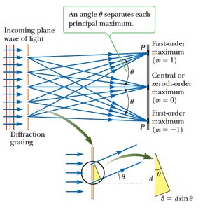
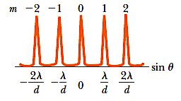
The condition for principal maxima is:
Each wavelength is diffracted at a specific angle, allowing precise measurement of wavelengths.
More lines per unit length (smaller \( d \)) result in larger angular separation between maxima.
Polarization
Nature of Polarized Light
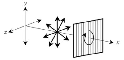
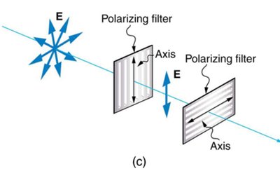
Light waves are transverse electromagnetic waves with oscillating electric and magnetic fields perpendicular to the direction of propagation. Polarization refers to the orientation of the electric field vector.
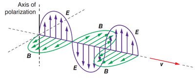
Unpolarized light consists of waves vibrating in all directions perpendicular to propagation.
Polarized light vibrates in a single plane.
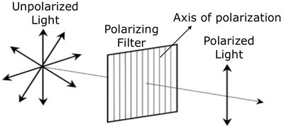
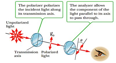
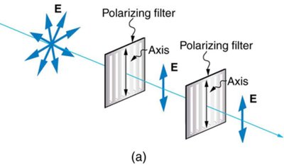
Polarizing Filters
Polarizing filters allow only light oscillating in a specific direction to pass through. When unpolarized light passes through a polarizer, the transmitted intensity is halved.
Two polarizers aligned: maximum transmission.
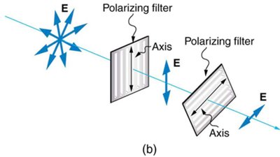
Two polarizers perpendicular: no transmission.
Intermediate angles: partial transmission.
Malus’s Law
Malus’s law quantifies the intensity of polarized light after passing through a second polarizing filter (analyzer) at an angle \( \theta \) to the first:
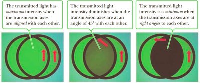
If \( \theta = 0 \), all light passes through (\( I = I_0 \)).
If \( \theta = 90^\circ \), no light passes through (\( I = 0 \)).
Applications of Polarization
Polarized sunglasses reduce glare by blocking horizontally polarized light reflected from surfaces.
3-D glasses use polarization to separate images for each eye, creating a three-dimensional effect.
Summary Table: Key Equations in Wave Optics
Phenomenon | Condition | Equation | Variables |
|---|---|---|---|
Double Slit (Bright) | Constructive | ||
Double Slit (Dark) | Destructive | ||
Fringe Position (Bright) | — | : screen distance | |
Single Slit (Dark) | Destructive | ||
Central Maximum Width | — | : slit width | |
Diffraction Grating | Maxima | : slit spacing | |
Malus’s Law | Polarization | : angle between axes |
