 Back
Backscratch
Study Guide - Smart Notes
 Tailored notes based on your materials, expanded with key definitions, examples, and context.
Chemical Bonds and Lewis Structures
Lewis Symbols and Electron Configurations
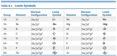
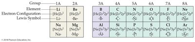
Lewis symbols are a visual representation of the valence electrons for each element, pioneered by Gilbert N. Lewis. These symbols help predict how atoms combine to form molecules and compounds.
Lewis Symbol: Consists of the element's chemical symbol surrounded by dots representing valence electrons.
Valence Electrons: Electrons in the outermost shell, crucial for chemical bonding.
Octet Rule: Atoms tend to gain, lose, or share electrons to achieve eight valence electrons.
Dot Placement: Dots are placed as far apart as possible around the symbol, up to eight.
Predicting Compound Formation Using Lewis Symbols
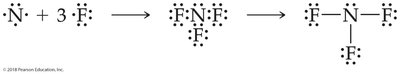
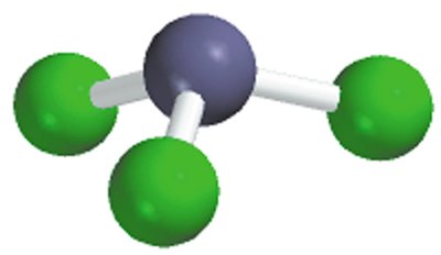
Lewis symbols can be used to predict the formula and structure of stable binary compounds. For example, nitrogen and fluorine combine to form nitrogen trifluoride (NF3), following the octet rule.
Example: N + 3F → NF3
Lewis Structure: Shows shared and unshared electron pairs.
Electronegativity and Bond Polarity
Electronegativity Trends
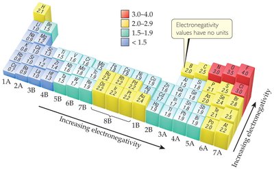
Electronegativity is the ability of an atom in a molecule to attract electrons to itself. It is a key factor in determining bond polarity.
Periodic Trend: Electronegativity increases across a period (left to right) and decreases down a group (top to bottom).
Bond Polarity: Determined by the difference in electronegativities between bonding atoms.
Polar Covalent Bonds and Electron Density
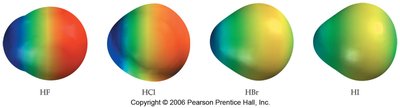
Atoms often share electrons unequally, resulting in polar covalent bonds. The greater the difference in electronegativity, the more polar the bond.
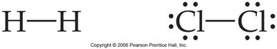
Nonpolar Covalent: Equal sharing of electrons (e.g., F2).
Polar Covalent: Unequal sharing (e.g., HF).
Ionic: Complete transfer of electrons (e.g., LiF).

Bond Polarity Examples and Dipole Moments
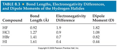
Bond polarity can be compared using electronegativity differences. Dipole moments arise in polar molecules and are zero in symmetric, nonpolar molecules.
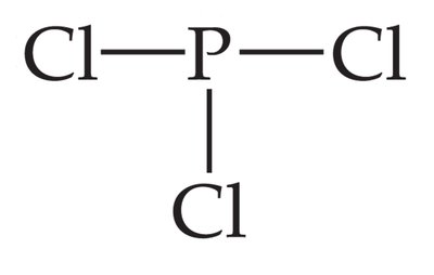
Example: B–Cl is more polar than C–Cl; P–F is more polar than P–Cl.
Dipole Moment (μ): A measure of bond polarity; μ = 0 for nonpolar molecules.
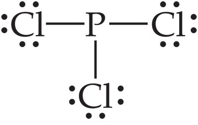
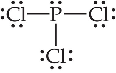
Drawing Lewis Structures
Steps for Drawing Lewis Structures
Lewis structures represent molecules, showing both bonding and nonbonding electrons. The process involves several systematic steps:
Step 1: Sum the valence electrons of all atoms in the molecule or ion.
Step 2: Identify the central atom (usually the least electronegative, except hydrogen).
Step 3: Connect outer atoms to the central atom with single bonds.
Step 4: Fill the octets of outer atoms with nonbonded electrons.
Step 5: Place any remaining electrons on the central atom.
Step 6: If the central atom lacks an octet, form multiple bonds as needed.
Step 7: For ions, enclose the structure in brackets and indicate the charge.
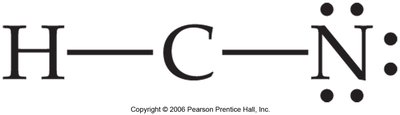
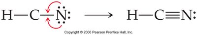
Lewis Structures with Multiple Bonds
When the central atom does not have a full octet after all electrons are placed, multiple bonds (double or triple) are formed.
Example: HCN requires a triple bond between C and N to satisfy the octet rule.
Hydrogen Exception: Hydrogen only forms one bond and never has a full octet.
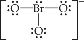
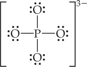
Lewis Structures for Polyatomic Ions
Polyatomic ions require careful electron counting and are represented with brackets and charges. Resonance structures may be necessary when multiple valid structures exist.
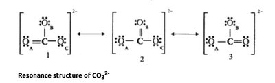
Example: BrO3– and CO32– have resonance structures.
Resonance: When more than one valid Lewis structure exists, the actual structure is a blend.

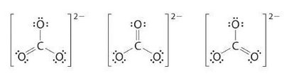
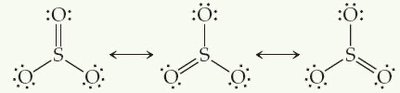
Resonance Structures
Perfect and Imperfect Resonance
Resonance structures are used to represent molecules where the actual bonding cannot be described by a single Lewis structure. Perfect resonance occurs when all atoms involved are the same; imperfect resonance occurs when they are not.
Example: CO32– and SO3 exhibit perfect resonance.
Bond Lengths: Resonance leads to bond lengths intermediate between single and double bonds.
Practice: Drawing Lewis Structures and Resonance
Practice exercises reinforce the concepts of electron counting, octet rule, and resonance.
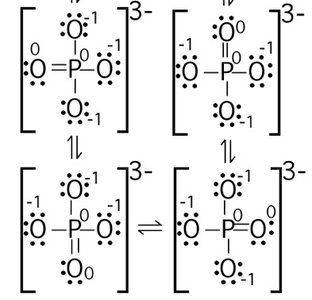
Example: Draw Lewis structures for ClO2–, PO43–, CS2, HNO3, HCOOH, and NO2–.
Resonance: Many polyatomic ions and molecules exhibit resonance, which must be shown in the structures.
Summary Table: Bond Classification by Electronegativity Difference
Electronegativity Difference | Bond Type |
|---|---|
0 | Nonpolar Covalent |
0 < and < ~2 | Polar Covalent |
≥ 2 | Ionic |
Key Takeaways: Lewis structures, electronegativity, and resonance are fundamental concepts for understanding chemical bonding and molecular structure in general chemistry.
