Ch 25: Current, Resistance, and EMF
Young & Freedman Calc - University Physics 14th Edition
Young & Freedman Calc14th EditionUniversity PhysicsISBN: 9780321973610Non è quello che usi tu?Cambia libro di testo
Capitolo 25, Problema 28a

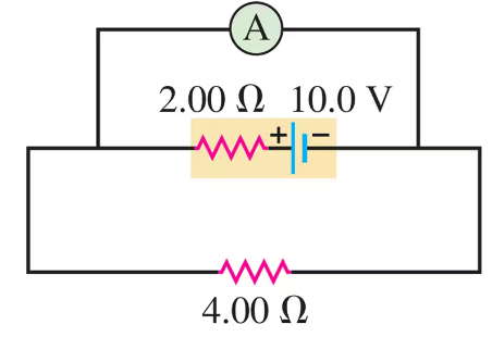
An idealized ammeter is connected to a battery as shown in Fig. E25.2825.28. Find the reading of the ammeter.
Circuit with ammeter, 10V battery, 2Ω and 4Ω resistors in series.

Guida verificata passo dopo passo
1
First, identify the components in the circuit: a battery with a voltage of 12.0 V, a resistor with a resistance of 16.8 Ω, and another resistor with a resistance of 12.0 Ω. The ammeter is connected in series with the 12.0 Ω resistor.
To find the reading of the ammeter, we need to calculate the current flowing through the circuit. Use Ohm's Law, which states that the current (I) is equal to the voltage (V) divided by the total resistance (R) in the circuit: I = V / R.
Calculate the total resistance in the circuit. Since the resistors are in series, the total resistance is the sum of the individual resistances: R_total = 16.8 Ω + 12.0 Ω.
Substitute the values into Ohm's Law: I = 12.0 V / R_total. This will give you the current flowing through the circuit, which is the reading of the ammeter.
Ensure that the units are consistent and check your calculations for any errors. The ammeter reading will be in amperes (A), which is the standard unit for current.

Risposta video verificata per un problema simile:

Questa soluzione video è stata consigliata dai nostri tutor come utile per risolvere questo problema.
Durata del video:
3m

Concetti chiave

Ecco i concetti essenziali che devi comprendere per rispondere correttamente alla domanda.

Ohm's Law

Ohm's Law is a fundamental principle in electronics and electrical engineering, stating that the current (I) through a conductor between two points is directly proportional to the voltage (V) across the two points and inversely proportional to the resistance (R) of the conductor. It is mathematically expressed as I = V/R. This law is essential for calculating the current in the circuit shown in the image.
Video consigliato:
Percorso guidato
03:07
Resistance and Ohm's Law

Series and Parallel Circuits

In a series circuit, components are connected end-to-end, so the same current flows through each component. In a parallel circuit, components are connected across the same voltage source, allowing the current to divide among the paths. The circuit in the image is a series circuit, as the resistors and the ammeter are connected in a single loop, affecting how the total resistance and current are calculated.
Video consigliato:
Percorso guidato
09:51
Combining Capacitors in Series & Parallel

Ideal Ammeter

An ideal ammeter is a device used to measure the current flowing through a circuit. It is assumed to have zero resistance, meaning it does not affect the current it measures. In the given circuit, the ammeter is connected in series with the resistors, and its reading will be the same as the current flowing through the entire circuit, calculated using Ohm's Law.
Video consigliato:
Percorso guidato
07:21
Ideal Gases and the Ideal Gas Law