
Ch 28: Fundamentals of Circuits
Knight Calc - Physics for Scientists and Engineers 5th Edition
Knight Calc5th EditionPhysics for Scientists and EngineersISBN: 9780137344796당신이 사용하는 게 아니라요?교과서 변경
28장, 문제 55

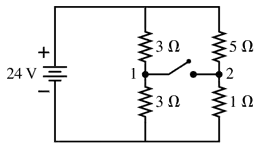
What are the battery current Ibat and the potential difference V₁ - V₂ between points 1 and 2 when the switch in FIGURE P28.55 is (a) open and (b) closed?
Schematic diagram of a circuit with a 24V battery, resistors, and a switch, labeled with points 1 and 2.

검증된 단계별 안내
1
Step 1: Analyze the circuit configuration when the switch is open. In this case, the 5 Ω and 1 Ω resistors are not connected, and the circuit consists of the battery, the two 3 Ω resistors in parallel, and the battery voltage of 24 V.
Step 2: Calculate the equivalent resistance of the two 3 Ω resistors in parallel using the formula for parallel resistance: 1R = 13 + 13. Simplify to find the equivalent resistance.
Step 3: Determine the battery current Ibat when the switch is open using Ohm's Law: I = VR, where V is the battery voltage and R is the equivalent resistance calculated in Step 2.
Step 4: Analyze the circuit configuration when the switch is closed. In this case, the 5 Ω and 1 Ω resistors are connected, forming a parallel combination with the 3 Ω resistors. Calculate the equivalent resistance of the entire circuit by first finding the combined resistance of the 5 Ω and 1 Ω resistors in parallel, then combining this result with the 3 Ω resistors.
Step 5: Calculate the battery current Ibat and the potential difference V₁ - V₂ when the switch is closed. Use Ohm's Law and the voltage divider rule to find the current through each branch and the potential difference between points 1 and 2.

비슷한 문제에 대한 검증된 영상 답변:

이 영상 해법은 위 문제에 도움이 된다고 튜터들이 추천한 것입니다.
도움이 되었나요?

주요 개념

질문에 올바르게 답하기 위해 반드시 이해해야 하는 핵심 개념들은 다음과 같습니다.

Ohm's Law

Ohm's Law states that the current (I) flowing through a conductor between two points is directly proportional to the voltage (V) across the two points and inversely proportional to the resistance (R) of the conductor. This relationship is expressed mathematically as V = I × R. Understanding this law is crucial for analyzing circuits, as it allows us to calculate current and voltage drops across resistors.
추천 영상:
가이드 코스
03:07
Resistance and Ohm's Law

Series and Parallel Circuits

In electrical circuits, components can be arranged in series or parallel configurations. In a series circuit, the same current flows through all components, while the total resistance is the sum of individual resistances. In a parallel circuit, the voltage across each component is the same, and the total current is the sum of the currents through each path. Recognizing these configurations is essential for determining the overall behavior of the circuit.
추천 영상:
가이드 코스
09:51
Combining Capacitors in Series & Parallel

Voltage Drop

Voltage drop refers to the reduction in voltage across a component in a circuit due to resistance. When current flows through a resistor, energy is dissipated as heat, resulting in a lower voltage at the end of the resistor compared to the beginning. Calculating the voltage drop across each resistor is important for understanding how voltage is distributed in a circuit and for solving for potential differences between points.
추천 영상:
가이드 코스
07:14
RMS Current and Voltage
관련 실천
교과서 질문

A 12 V car battery dies not so much because its voltage drops but because chemical reactions increase its internal resistance. A good battery connected with jumper cables can both start the engine and recharge the dead battery. Consider the automotive circuit of FIGURE P28.64. How much current is the dead battery alone able to drive through the starter motor?

1729
views
교과서 질문

A lightbulb is in series with a 2.0 Ω resistor. The lightbulb dissipates 10 W when this series circuit is connected to a 9.0 V battery. What is the current through the lightbulb? There are two possible answers; give both of them.

88
views
교과서 질문

Suppose you have resistors 2.5 Ω, 3.5 Ω, and 4.5 Ω and a 100 V power supply. What is the ratio of the total power delivered to the resistors if they are connected in parallel to the total power delivered if they are connected in series?

62
views
교과서 질문

What is the current through the 10 Ω resistor in FIGURE P28.61? Is the current from left to right or right to left?

232
views
교과서 질문

Load resistor R is attached to a battery of emf and internal resistance r. For what value of the resistance R, in terms of ∈ and r, will the power dissipated by the load resistor be a maximum?

572
views
교과서 질문

A circuit you're building needs an ammeter that goes from 0 mA to a full-scale reading of 50 mA. Unfortunately, the only ammeter in the storeroom goes from 0 μA to a full-scale reading of only 500 μA. Fortunately, you've just finished a physics class, and you realize that you can make this ammeter work by putting a resistor in parallel with it, as shown in FIGURE P28.56. You've measured that the resistance of the ammeter is 50.0 Ω, not the 0 Ω of an ideal ammeter. What is the effective resistance of your ammeter?

63
views