

Ch 30: Electromagnetic Induction
Knight Calc - Physics for Scientists and Engineers 5th Edition
Knight Calc5th EditionPhysics for Scientists and EngineersISBN: 9780137344796당신이 사용하는 게 아니라요?교과서 변경
30장, 문제 57a

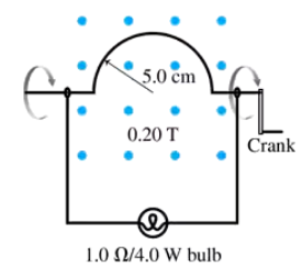
CALC Your camping buddy has an idea for a light to go inside your tent. He happens to have a powerful (and heavy!) horseshoe magnet that he bought at a surplus store. This magnet creates a 0.20 T field between two pole tips 10 cm apart. His idea is to build the hand-cranked generator shown in FIGURE P30.57. He thinks you can make enough current to fully light a 1.0 Ω lightbulb rated at 4.0 W. That's not super bright, but it should be plenty of light for routine activities in the tent. Find an expression for the induced current as a function of time if you turn the crank at frequency f. Assume that the semicircle is at its highest point at t = 0 s.

검증된 단계별 안내
1
Step 1: Understand the setup. The hand-cranked generator consists of a semicircular loop of wire rotating in a uniform magnetic field of 0.20 T. The loop has a radius of 5.0 cm, and the magnetic field is perpendicular to the plane of the loop. The goal is to find an expression for the induced current as a function of time, given the rotation frequency f.
Step 2: Calculate the area of the semicircular loop. The area of a semicircle is given by \( A = \frac{1}{2} \pi r^2 \), where \( r \) is the radius of the loop. Substitute \( r = 0.05 \, \text{m} \) to find the area.
Step 3: Use Faraday's Law of Induction to find the induced electromotive force (EMF). Faraday's Law states \( \mathcal{E} = - \frac{d\Phi_B}{dt} \), where \( \Phi_B \) is the magnetic flux. Magnetic flux is given by \( \Phi_B = B \cdot A \cdot \cos(\theta) \), where \( \theta \) is the angle between the magnetic field and the normal to the loop. As the loop rotates, \( \theta \) changes with time as \( \theta = \omega t \), where \( \omega = 2 \pi f \) is the angular frequency.
Step 4: Differentiate the magnetic flux \( \Phi_B \) with respect to time to find the induced EMF. Substitute \( \Phi_B = B \cdot A \cdot \cos(\omega t) \) into \( \mathcal{E} = - \frac{d\Phi_B}{dt} \). The derivative of \( \cos(\omega t) \) is \( -\omega \sin(\omega t) \), so \( \mathcal{E} = B \cdot A \cdot \omega \cdot \sin(\omega t) \).
Step 5: Use Ohm's Law to find the induced current. Ohm's Law states \( I = \frac{\mathcal{E}}{R} \), where \( R \) is the resistance of the circuit. Substitute \( \mathcal{E} = B \cdot A \cdot \omega \cdot \sin(\omega t) \) and \( R = 1.0 \, \Omega \) to find \( I(t) = \frac{B \cdot A \cdot \omega \cdot \sin(\omega t)}{R} \).

비슷한 문제에 대한 검증된 영상 답변:

이 영상 해법은 위 문제에 도움이 된다고 튜터들이 추천한 것입니다.
도움이 되었나요?

주요 개념

질문에 올바르게 답하기 위해 반드시 이해해야 하는 핵심 개념들은 다음과 같습니다.

Electromagnetic Induction

Electromagnetic induction is the process by which a changing magnetic field within a closed loop induces an electromotive force (EMF) in the wire. This principle, described by Faraday's Law, states that the induced EMF is proportional to the rate of change of the magnetic flux through the loop. In this scenario, the hand-cranked generator creates a changing magnetic environment as the semicircular conductor moves through the magnetic field, generating current.
추천 영상:
가이드 코스
05:42
Introduction to Induction

Ohm's Law

Ohm's Law relates the voltage (V), current (I), and resistance (R) in an electrical circuit, expressed as V = IR. This fundamental principle allows us to calculate the current flowing through the circuit when a voltage is applied across a resistor. In this case, knowing the resistance of the lightbulb (1.0 Ω) and the power rating (4.0 W), we can determine the voltage needed to light the bulb and subsequently the current that will flow when the generator is cranked.
추천 영상:
가이드 코스
03:07
Resistance and Ohm's Law

Frequency and Angular Frequency

Frequency (f) refers to the number of cycles per second in a periodic motion, while angular frequency (ω) is related to frequency by the equation ω = 2πf. In the context of the hand-cranked generator, the frequency of cranking affects how quickly the semicircular conductor moves through the magnetic field, which in turn influences the rate of change of magnetic flux and the induced current. Understanding this relationship is crucial for deriving the expression for induced current as a function of time.
추천 영상:
가이드 코스
05:08
Circumference, Period, and Frequency in UCM
관련 실천
교과서 질문

INT A 20-cm-long, zero-resistance slide wire moves outward, on zero-resistance rails, at a steady speed of 10 m/s in a 0.10 T magnetic field. (See Figure 30.26.) On the opposite side, a 1.0 Ω carbon resistor completes the circuit by connecting the two rails. The mass of the resistor is 50 mg. If the wire is pulled for 10 s, what is the temperature increase of the carbon? The specific heat of carbon is 710 J/kg K.

132
views
교과서 질문

INT You've decided to make the magnetic projectile launcher shown in FIGURE P30.58 for your science project. An aluminum bar slides along metal rails through a magnetic field B. The switch closes at t = 0 s, while the bar is at rest, and a battery of emf εbat starts a current flowing around the loop. The battery has internal resistance r. The resistances of the rails, which are separated by distance l, and the bar are effectively zero. Evaluate vterm for εbat = 1.0 V, r = 0.10 Ω, l = 6.0 cm, and B = 0.50 T.

53
views
교과서 질문

INT A 20-cm-long, zero-resistance slide wire moves outward, on zero-resistance rails, at a steady speed of 10 m/s in a 0.10 T magnetic field. (See Figure 30.26.) On the opposite side, a 1.0 Ω carbon resistor completes the circuit by connecting the two rails. The mass of the resistor is 50 mg. How much force is needed to pull the wire at this speed?

236
views
교과서 질문

INT A 20-cm-long, zero-resistance slide wire moves outward, on zero-resistance rails, at a steady speed of 10 m/s in a 0.10 T magnetic field. (See Figure 30.26.) On the opposite side, a 1.0 Ω carbon resistor completes the circuit by connecting the two rails. The mass of the resistor is 50 mg. What is the induced current in the circuit?

97
views
교과서 질문

INT You've decided to make the magnetic projectile launcher shown in FIGURE P30.58 for your science project. An aluminum bar slides along metal rails through a magnetic field B. The switch closes at t = 0 s, while the bar is at rest, and a battery of emf εbat starts a current flowing around the loop. The battery has internal resistance r. The resistances of the rails, which are separated by distance l, and the bar are effectively zero. Show that the bar reaches a terminal speed vterm, and find an expression for vterm.

48
views
교과서 질문

CALC Your camping buddy has an idea for a light to go inside your tent. He happens to have a powerful (and heavy!) horseshoe magnet that he bought at a surplus store. This magnet creates a 0.20 T field between two pole tips 10 cm apart. His idea is to build the hand-cranked generator shown in FIGURE P30.57. He thinks you can make enough current to fully light a 1.0 Ω lightbulb rated at 4.0 W. That's not super bright, but it should be plenty of light for routine activities in the tent. With what frequency will you have to turn the crank for the maximum current to fully light the bulb? Is this feasible?

59
views