Ch 32: AC Circuits
Knight Calc - Physics for Scientists and Engineers 5th Edition
Knight Calc5th EditionPhysics for Scientists and EngineersISBN: 9780137344796당신이 사용하는 게 아니라요?교과서 변경
32장, 문제 70b

A series RLC circuit with ε0 = 10.0 V consists of a 1.0 Ω resistor, a 1.0 μH inductor, and a 1.0 μF capacitor. What is V1 at ω = ω0 and at ω = ω1?

검증된 단계별 안내
1
Identify the key components of the series RLC circuit: a resistor (R = 1.0 Ω), an inductor (L = 1.0 μH = 1.0 × 10⁻⁶ H), and a capacitor (C = 1.0 μF = 1.0 × 10⁻⁶ F). The source voltage is ε₀ = 10.0 V.
Determine the resonant angular frequency (ω₀) of the circuit using the formula: ω0=1LC. Substitute the values of L and C to calculate ω₀.
At resonance (ω = ω₀), the inductive reactance (XL=ωL) and capacitive reactance (XC=1ωC) cancel each other out, leaving only the resistor. Use Ohm's law (V1=IR) to find V₁, where I is the current.
For ω = ω₁ (a frequency other than resonance), calculate the total impedance (Z) of the circuit using the formula: Z=R2+(XL-XC)2. Substitute the values of R, XL, and XC to find Z.
Once Z is determined for ω = ω₁, use Ohm's law again to find V₁: V1=IR, where the current I is given by I=ε0Z. Substitute the values to calculate V₁.

비슷한 문제에 대한 검증된 영상 답변:

이 영상 해법은 위 문제에 도움이 된다고 튜터들이 추천한 것입니다.
도움이 되었나요?

주요 개념

질문에 올바르게 답하기 위해 반드시 이해해야 하는 핵심 개념들은 다음과 같습니다.

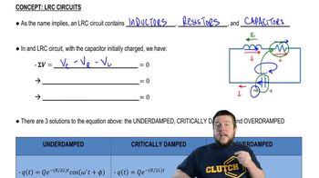
RLC Circuit

An RLC circuit is an electrical circuit consisting of a resistor (R), inductor (L), and capacitor (C) connected in series or parallel. The behavior of the circuit is influenced by the values of these components, particularly in response to alternating current (AC) signals. The circuit can exhibit resonance, where the inductive and capacitive reactances cancel each other out, leading to maximum voltage across the components.
추천 영상:

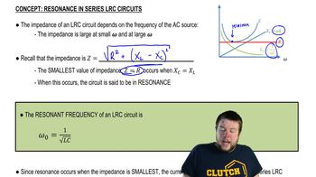
Resonant Frequency (ω₀)

The resonant frequency (ω₀) of an RLC circuit is the frequency at which the inductive reactance equals the capacitive reactance, resulting in maximum current flow and minimal impedance. It is calculated using the formula ω₀ = 1/√(LC), where L is the inductance and C is the capacitance. At this frequency, the circuit can store and transfer energy efficiently between the inductor and capacitor.
추천 영상:
가이드 코스
05:23
Resonance in Series LRC Circuits

Voltage Across Components (V₁)

The voltage across a specific component in an RLC circuit, denoted as V₁, can vary depending on the frequency of the applied voltage source. At resonance (ω = ω₀), the voltage across the components can be significantly higher than the source voltage due to the energy oscillation between the inductor and capacitor. At other frequencies (ω = ω₁), the voltage distribution changes, influenced by the impedance of the circuit.
추천 영상:
가이드 코스
07:14
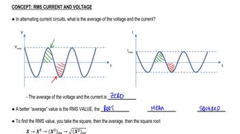
RMS Current and Voltage