Ch 32: AC Circuits
Knight Calc - Physics for Scientists and Engineers 5th Edition
Knight Calc5th EditionPhysics for Scientists and EngineersISBN: 9780137344796당신이 사용하는 게 아니라요?교과서 변경
32장, 문제 72b

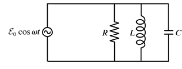
Consider the parallel RLC circuit shown in FIGURE CP32.72. What is I in the limits ω→0 and ω→∞?

검증된 단계별 안내
1
Step 1: Analyze the circuit components. The circuit consists of a resistor (R), an inductor (L), and a capacitor (C) connected in parallel to an AC voltage source with an angular frequency ω. The current I in the circuit depends on the impedance of each component and the frequency of the source.
Step 2: Consider the limit ω → 0 (low frequency). At very low frequencies, the capacitor acts as an open circuit because its reactance is very high (X_C = 1/(ωC)), and the inductor acts as a short circuit because its reactance is very low (X_L = ωL). Therefore, the current flows primarily through the resistor and the inductor.
Step 3: Consider the limit ω → ∞ (high frequency). At very high frequencies, the capacitor acts as a short circuit because its reactance becomes very small (X_C = 1/(ωC)), and the inductor acts as an open circuit because its reactance becomes very large (X_L = ωL). Therefore, the current flows primarily through the resistor and the capacitor.
Step 4: Write the expressions for the impedance of each component. The impedance of the resistor is Z_R = R, the impedance of the inductor is Z_L = jωL, and the impedance of the capacitor is Z_C = 1/(jωC). Use these expressions to analyze the current contributions from each component in the circuit at the given frequency limits.
Step 5: Combine the contributions of the components to determine the total current I. At ω → 0, the current is dominated by the resistor and inductor. At ω → ∞, the current is dominated by the resistor and capacitor. Use the parallel impedance formula to calculate the total impedance and current in each case.

비슷한 문제에 대한 검증된 영상 답변:

이 영상 해법은 위 문제에 도움이 된다고 튜터들이 추천한 것입니다.
도움이 되었나요?

주요 개념

질문에 올바르게 답하기 위해 반드시 이해해야 하는 핵심 개념들은 다음과 같습니다.

Impedance in RLC Circuits

In a parallel RLC circuit, the total impedance is determined by the individual impedances of the resistor (R), inductor (L), and capacitor (C). The impedance varies with frequency, affecting the current (I) flowing through the circuit. At low frequencies (ω→0), the inductor behaves like a short circuit, while the capacitor acts like an open circuit, and at high frequencies (ω→∞), the inductor behaves like an open circuit, and the capacitor acts like a short circuit.
추천 영상:
08:40
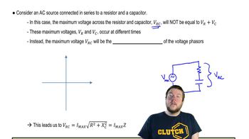
Impedance in AC Circuits

Resonance

Resonance occurs in RLC circuits when the inductive and capacitive reactances are equal, leading to maximum current flow at a specific frequency. However, in the context of the limits ω→0 and ω→∞, resonance is not directly applicable, but understanding it helps in analyzing how the circuit responds to different frequencies and how the current varies accordingly.
추천 영상:
05:23
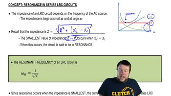
Resonance in Series LRC Circuits

Current Behavior in AC Circuits

In alternating current (AC) circuits, the behavior of current is influenced by the frequency of the source. At ω→0, the circuit behaves predominantly resistively, leading to maximum current through the resistor. Conversely, at ω→∞, the circuit's behavior is dominated by the capacitor, resulting in minimal current flow, as the capacitor blocks high-frequency signals.
추천 영상:
03:45
Current in a Parallel RC AC Circuit