Ch 31: Alternating Current
Young & Freedman Calc - University Physics 14th Edition
Young & Freedman Calc14th EditionUniversity PhysicsISBN: 9780321973610당신이 사용하는 게 아니라요?교과서 변경
31장, 문제 25a

A series ac circuit contains a 250-Ω resistor, a 15-mH inductor, a 3.5-μF capacitor, and an ac power source of voltage amplitude 45 V operating at an angular frequency of 360 rad/s.What is the power factor of this circuit?

검증된 단계별 안내
1
Understand the concept of power factor in an AC circuit. The power factor is defined as the cosine of the phase angle (φ) between the total voltage and the total current in the circuit. It is given by the formula: cos(φ).
Calculate the inductive reactance (XL) using the formula: XL=ωL, where ω is the angular frequency and L is the inductance.
Calculate the capacitive reactance (XC) using the formula: XC=1ωC, where C is the capacitance.
Determine the total impedance (Z) of the circuit using the formula: Z=R2+(XL-XC)2, where R is the resistance.
Calculate the power factor using the formula: cos(φ)=RZ, where R is the resistance and Z is the total impedance.

비슷한 문제에 대한 검증된 영상 답변:

이 영상 해법은 위 문제에 도움이 된다고 튜터들이 추천한 것입니다.
영상 길이:
5m
도움이 되었나요?

주요 개념

질문에 올바르게 답하기 위해 반드시 이해해야 하는 핵심 개념들은 다음과 같습니다.

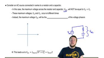
Impedance in AC Circuits

Impedance is the total opposition a circuit offers to the flow of alternating current, combining resistance, inductive reactance, and capacitive reactance. In a series AC circuit, impedance (Z) is calculated using Z = √(R² + (X_L - X_C)²), where R is resistance, X_L is inductive reactance, and X_C is capacitive reactance. Understanding impedance is crucial for determining the circuit's behavior at different frequencies.
추천 영상:
08:40
Impedance in AC Circuits

Reactance

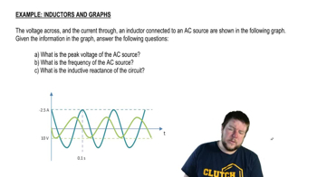
Reactance is the opposition to the change in current flow in an AC circuit due to inductors and capacitors. Inductive reactance (X_L) is given by X_L = ωL, and capacitive reactance (X_C) is given by X_C = 1/(ωC), where ω is the angular frequency, L is inductance, and C is capacitance. Reactance affects the phase difference between voltage and current, influencing the power factor.
추천 영상:
03:36
Inductors and Graphs

Power Factor

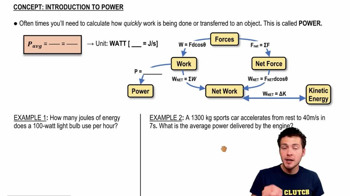
The power factor in an AC circuit is the ratio of real power used to do work to apparent power flowing in the circuit, expressed as cos(φ), where φ is the phase angle between voltage and current. It indicates how effectively electrical power is converted into useful work, with a power factor of 1 being ideal. Calculating the power factor involves understanding the phase relationship between circuit elements and their reactances.
추천 영상:
06:00
Power
관련 실천
교과서 질문

In an L-R-C series circuit, the components have the following values: L = 20.0 mH, C = 140 nF, and R = 350 Ω.The generator has an rms voltage of 120 V and a frequency of 1.25 kHz. Determine (a) the power supplied by the generator and (b) the power dissipated in the resistor.

1884
views
교과서 질문

Off to Europe! You plan to take your hair dryer to Europe, where the electrical outlets put out 240 V instead of the 120 V seen in the United States. The dryer puts out 1600 W at 120 V. (b) What current will your dryer draw from a European outlet? (c) What resistance will your dryer appear to have when operated at 240 V?

1618
views
교과서 질문

Off to Europe! You plan to take your hair dryer to Europe, where the electrical outlets put out 240 V instead of the 120 V seen in the United States. The dryer puts out 1600 W at 120 V. What could you do to operate your dryer via the 240 V line in Europe?

1645
views
교과서 질문

An L-R-C series circuit with L = 0.120 H, R = 240 Ω, and C = 7.30 μF carries an rms current of 0.450 A with a frequency of 400 Hz. What are the phase angle and power factor for this circuit?

1782
views
교과서 질문

An L-R-C series circuit is connected to a 120-Hz ac source that has Vrms = 80.0 V. The circuit has a resistance of 75.0 Ω and an impedance at this frequency of 105 Ω. What average power is delivered to the circuit by the source?

1791
views
교과서 질문

A Step-Down Transformer. A transformer connected to a 120 V (rms) ac line is to supply 12.0 V (rms) to a portable electronic device. The load resistance in the secondary is 5.00 Ω. What should the ratio of primary to secondary turns of the transformer be?

1709
views