 Back
BackElectric Current, Resistance, Circuits, and Magnetism: Study Notes
Study Guide - Smart Notes
 Tailored notes based on your materials, expanded with key definitions, examples, and context.
Electric Current and Circuits
Definition and Direction of Electric Current
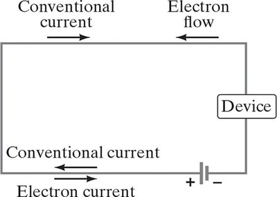
Electric current is defined as the rate of flow of electric charge through a conductor. By convention, the direction of current is taken as the direction in which positive charges would flow, even though in most conductors, electrons (negative charges) are the actual charge carriers and move in the opposite direction.
Conventional current: Direction positive charges would move.
Electron flow: Actual direction of electron movement, opposite to conventional current.
Electric Circuits
A complete (closed) circuit allows current to flow continuously. If the circuit is broken (open), current cannot flow.
Ohm’s Law and Resistance
Ohm’s Law
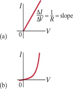
Ohm’s law states that the current through a conductor between two points is directly proportional to the voltage across the two points, provided the temperature remains constant. The proportionality constant is the resistance.
Mathematical form:
Ohmic materials: Materials that obey Ohm’s law (linear - relationship).
Nonohmic materials: Materials that do not obey Ohm’s law (nonlinear - relationship).
Unit of resistance: Ohm (), where .
Clarifications about Current and Resistance
Batteries maintain a nearly constant potential difference; current varies with resistance.
Resistance is a property of a material or device, not of the current.
Current is not a vector, but it has a direction.
Charge is conserved; it does not get used up in a circuit.
Types of Electric Current
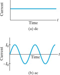
Direct Current (DC) and Alternating Current (AC)
There are two main types of electric current:
Direct Current (DC): Current flows steadily in one direction (e.g., from a battery).
Alternating Current (AC): Current varies sinusoidally with time, reversing direction periodically (e.g., household power supply).
Resistivity and Temperature Dependence
Resistivity
Resistivity () is a material property that quantifies how strongly a given material opposes the flow of electric current. For most conductors, resistivity increases with temperature:
Temperature dependence:
is the temperature coefficient of resistivity.
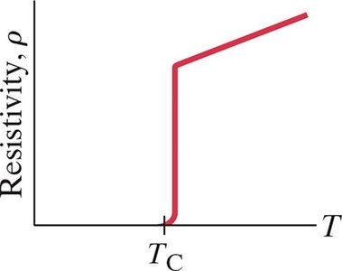
Superconductivity
Some materials exhibit a sudden drop in resistivity to zero at a critical temperature (). These are called superconductors.
Electric Power
Power in Electric Circuits
Electric power is the rate at which energy is transferred or converted by an electric circuit:
Formula:
Unit: Watt (W)
Practical Circuits and Safety
Household Circuits and Safety Devices
High currents can cause wires to overheat and potentially start fires. Safety devices such as fuses (single-use) and circuit breakers (resettable) are used to prevent excessive current flow.
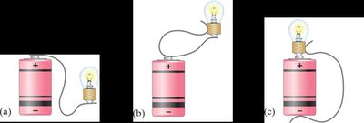
Example: Connecting a Battery to a Bulb
To light a bulb with a battery and a single wire, the wire must connect the bottom of the bulb to one terminal and the side of the bulb to the other terminal, completing the circuit. Incorrect connections will not complete the circuit and the bulb will not light.
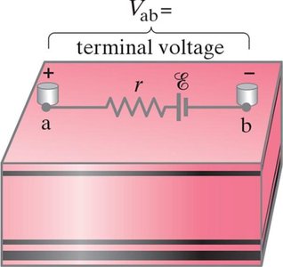
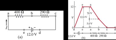
Internal Resistance and Terminal Voltage
EMF and Internal Resistance
Real batteries have internal resistance (), which causes the terminal voltage () to be less than the ideal emf () when current flows:
Terminal voltage:
Resistors in Series and Parallel
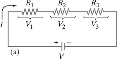
Series Circuits
In a series circuit, all components share the same current. The total (equivalent) resistance is the sum of individual resistances:
The total voltage is divided among the resistors:
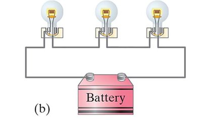
Parallel Circuits
In a parallel circuit, all components share the same voltage. The total current is the sum of the currents through each branch, and the reciprocal of the equivalent resistance is the sum of the reciprocals of the individual resistances:
Kirchhoff’s Rules
Junction Rule
The sum of currents entering a junction equals the sum of currents leaving the junction (conservation of charge).
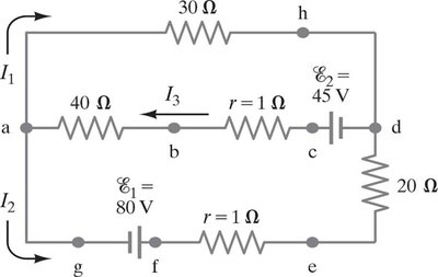
Loop Rule
The sum of the changes in potential around any closed loop is zero (conservation of energy).
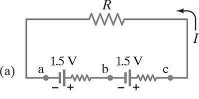
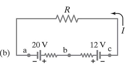
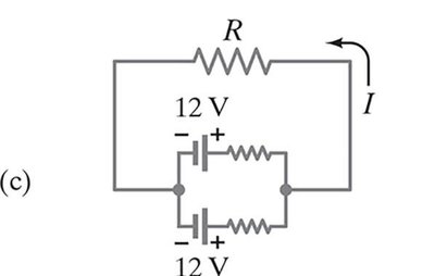
EMFs in Series and Parallel
Series and Parallel Combinations of EMFs
EMFs in series (same direction): Total voltage is the sum of individual voltages.
EMFs in series (opposite direction): Total voltage is the difference; the lower-voltage battery may be charged.
EMFs in parallel: Only makes sense if voltages are equal; increases available current.
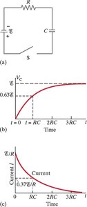
RC Circuits (Resistor and Capacitor in Series)
Charging and Discharging a Capacitor
When a capacitor is connected in series with a resistor and a voltage source, it charges over time. The time constant characterizes how quickly the capacitor charges or discharges.
Charging:
Discharging:
Summary Table: Right-Hand Rules for Magnetism
The right-hand rules are used to determine the direction of magnetic fields, forces, and currents in various situations involving magnetism.
Physical Situation | How to Orient Right Hand | Result |
|---|---|---|
Magnetic field produced by current (RHR-1) | Wrap fingers around wire with thumb pointing in direction of current | Fingers curl in direction of |
Force on electric current due to magnetic field (RHR-2) | Fingers point straight along current , bend fingers along magnetic field | Thumb points in direction of force |
Force on a positive electric charge due to magnetic field | Fingers point along particle's velocity , then bend toward | Thumb points in direction of force |
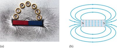
Magnetism: Magnets and Magnetic Fields
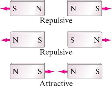
Magnetic Poles and Field Lines
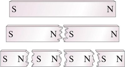
Magnets have two poles: north (N) and south (S). Like poles repel, unlike poles attract. Magnetic field lines emerge from the north pole and enter the south pole, forming closed loops.
Cutting a magnet results in two smaller magnets, each with a north and south pole.
Magnetic fields can be visualized with field lines; they are always closed loops.
No magnetic monopoles exist.
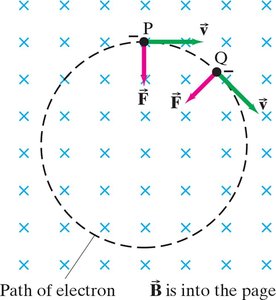
Force on a Moving Charge in a Magnetic Field
A charged particle moving perpendicular to a uniform magnetic field experiences a force perpendicular to both its velocity and the field, causing it to move in a circular path.
Additional info: These notes cover the core concepts of electric current, resistance, Ohm's law, series and parallel circuits, Kirchhoff's rules, RC circuits, and the basics of magnetism, as outlined in standard college physics curricula (Chapters 25-28).
