Ch 28: Fundamentals of Circuits
Knight Calc - Physics for Scientists and Engineers 5th Edition
Knight Calc5th EditionPhysics for Scientists and EngineersISBN: 9780137344796당신이 사용하는 게 아니라요?교과서 변경
28장, 문제 1

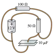
Draw a circuit diagram for the circuit of FIGURE EX28.1.
Circuit diagram showing a 12V battery, resistors of 100Ω and 50Ω, and a capacitor of 10μF connected in a loop.

검증된 단계별 안내
1
Understand the components of the circuit in FIGURE EX28.1. Identify all elements such as resistors, batteries, capacitors, switches, or any other components mentioned in the figure.
Determine the connections between the components. For example, check if the resistors are connected in series or parallel, how the battery is connected, and whether there are any junctions or branches in the circuit.
Use standard circuit diagram symbols to represent each component. For instance, use a zigzag line for resistors, a pair of parallel lines for a battery, and straight lines for wires.
Arrange the components in the diagram to match the physical layout or logical connections shown in FIGURE EX28.1. Ensure that the connections between components are accurately represented.
Label all components and values (e.g., resistance, voltage, capacitance) as provided in the figure. This ensures clarity and completeness of the circuit diagram.

비슷한 문제에 대한 검증된 영상 답변:

이 영상 해법은 위 문제에 도움이 된다고 튜터들이 추천한 것입니다.
도움이 되었나요?

주요 개념

질문에 올바르게 답하기 위해 반드시 이해해야 하는 핵심 개념들은 다음과 같습니다.

Circuit Diagram

A circuit diagram is a visual representation of an electrical circuit, showing the components and their connections. It uses standardized symbols to represent elements like resistors, capacitors, and power sources, allowing for easy understanding and analysis of the circuit's function. Properly labeling the components and connections is crucial for clarity and accuracy.
추천 영상:
가이드 코스
08:07
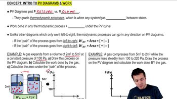
Work and PV Diagrams

Ohm's Law

Ohm's Law is a fundamental principle in electronics that relates voltage (V), current (I), and resistance (R) in a circuit. It states that V = I × R, meaning the voltage across a conductor is directly proportional to the current flowing through it, provided the temperature remains constant. Understanding this law is essential for analyzing circuit behavior and calculating unknown values.
추천 영상:
가이드 코스
03:07
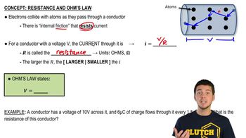
Resistance and Ohm's Law

Series and Parallel Circuits

Series and parallel circuits are two basic configurations for connecting components. In a series circuit, components are connected end-to-end, so the same current flows through each component, while the total resistance is the sum of individual resistances. In a parallel circuit, components are connected across the same voltage source, allowing multiple paths for current, which affects the total resistance and current distribution. Recognizing these configurations is vital for circuit analysis.
추천 영상:
가이드 코스
09:51
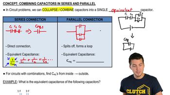
Combining Capacitors in Series & Parallel