Ch 25: Current, Resistance, and EMF
Young & Freedman Calc - University Physics 14th Edition
Young & Freedman Calc14th EditionUniversity PhysicsISBN: 9780321973610당신이 사용하는 게 아니라요?교과서 변경
25장, 문제 28a

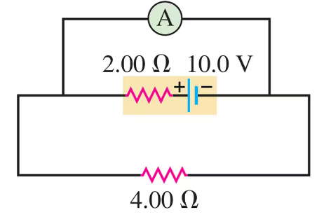
An idealized ammeter is connected to a battery as shown in Fig. E25.2825.28. Find the reading of the ammeter.
Circuit with ammeter, 10V battery, 2Ω and 4Ω resistors in series.

검증된 단계별 안내
1
First, identify the components in the circuit: a battery with a voltage of 12.0 V, a resistor with a resistance of 16.8 Ω, and another resistor with a resistance of 12.0 Ω. The ammeter is connected in series with the 12.0 Ω resistor.
To find the reading of the ammeter, we need to calculate the current flowing through the circuit. Use Ohm's Law, which states that the current (I) is equal to the voltage (V) divided by the total resistance (R) in the circuit: I = V / R.
Calculate the total resistance in the circuit. Since the resistors are in series, the total resistance is the sum of the individual resistances: R_total = 16.8 Ω + 12.0 Ω.
Substitute the values into Ohm's Law: I = 12.0 V / R_total. This will give you the current flowing through the circuit, which is the reading of the ammeter.
Ensure that the units are consistent and check your calculations for any errors. The ammeter reading will be in amperes (A), which is the standard unit for current.

비슷한 문제에 대한 검증된 영상 답변:

이 영상 해법은 위 문제에 도움이 된다고 튜터들이 추천한 것입니다.
영상 길이:
3m
도움이 되었나요?

주요 개념

질문에 올바르게 답하기 위해 반드시 이해해야 하는 핵심 개념들은 다음과 같습니다.

Ohm's Law

Ohm's Law is a fundamental principle in electronics and electrical engineering, stating that the current (I) through a conductor between two points is directly proportional to the voltage (V) across the two points and inversely proportional to the resistance (R) of the conductor. It is mathematically expressed as I = V/R. This law is essential for calculating the current in the circuit shown in the image.
추천 영상:
가이드 코스
03:07
Resistance and Ohm's Law

Series and Parallel Circuits

In a series circuit, components are connected end-to-end, so the same current flows through each component. In a parallel circuit, components are connected across the same voltage source, allowing the current to divide among the paths. The circuit in the image is a series circuit, as the resistors and the ammeter are connected in a single loop, affecting how the total resistance and current are calculated.
추천 영상:
가이드 코스
09:51
Combining Capacitors in Series & Parallel

Ideal Ammeter

An ideal ammeter is a device used to measure the current flowing through a circuit. It is assumed to have zero resistance, meaning it does not affect the current it measures. In the given circuit, the ammeter is connected in series with the resistors, and its reading will be the same as the current flowing through the entire circuit, calculated using Ohm's Law.
추천 영상:
가이드 코스
07:21
Ideal Gases and the Ideal Gas Law