
Ch. 30 - Inductance, Electromagnetic Oscillations, and AC Circuits
Giancoli Douglas - Physics for Scientists and Engineers 5th edition
Giancoli Douglas5th editionPhysics for Scientists and EngineersISBN: 9780137488179Not the one you use?Change textbook
Chapter 29, Problem 84b

In some experiments, very tiny distances or spaces ( ≈ nm ) can be measured by using capacitance. Consider forming an LC circuit using a parallel-plate capacitor with plate area A, and a known inductance L. When the plate separation is changed by ∆x, the circuit’s oscillation frequency will change by ∆f. Show that ∆x/x ≈ 2(∆f/f).

Verified step by step guidance
1
Start by recalling the formula for the capacitance of a parallel-plate capacitor: C = (ε₀A)/x, where ε₀ is the permittivity of free space, A is the plate area, and x is the plate separation.
The oscillation frequency of an LC circuit is given by f = 1/(2π√(LC)). Substitute the expression for C into this formula to express f in terms of x: f = 1/(2π√(L(ε₀A)/x)).
Simplify the expression for f: f = 1/(2π)√(x/(Lε₀A)). Notice that f is proportional to the square root of x.
To find the relationship between changes in x and f, take the derivative of f with respect to x, or equivalently use the proportionality: ∆f/f = (1/2)(∆x/x).
Rearrange the proportionality to isolate ∆x/x: ∆x/x ≈ 2(∆f/f). This shows the desired relationship between the fractional changes in plate separation and oscillation frequency.

Verified video answer for a similar problem:

This video solution was recommended by our tutors as helpful for the problem above.
Video duration:
4m
Was this helpful?

Key Concepts

Here are the essential concepts you must grasp in order to answer the question correctly.

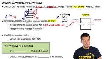
Capacitance

Capacitance is the ability of a system to store electric charge per unit voltage. In a parallel-plate capacitor, it is determined by the area of the plates (A) and the distance between them (d), following the formula C = ε₀(A/d), where ε₀ is the permittivity of free space. Changes in plate separation directly affect capacitance, which in turn influences the oscillation frequency of an LC circuit.
Recommended video:
Guided course
08:02
Capacitors & Capacitance (Intro)

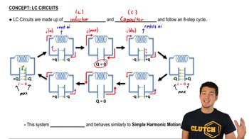
LC Circuit

An LC circuit is an electrical circuit consisting of an inductor (L) and a capacitor (C) connected together. It can oscillate at a natural frequency determined by the values of L and C, given by the formula f = 1/(2π√(LC)). The frequency of oscillation is sensitive to changes in capacitance, which can occur due to variations in plate separation in a parallel-plate capacitor.
Recommended video:

Frequency Change Relation

The relationship between changes in frequency (∆f) and changes in physical parameters (like plate separation ∆x) in an LC circuit can be derived from the dependence of capacitance on distance. The approximation ∆x/x ≈ 2(∆f/f) indicates that relative changes in plate separation are proportional to twice the relative changes in frequency, highlighting the sensitivity of the circuit's oscillation frequency to small physical alterations.
Recommended video:
Guided course
05:08
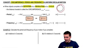
Circumference, Period, and Frequency in UCM
Related Practice
Textbook Question

In some experiments, very tiny distances or spaces ( ≈ nm ) can be measured by using capacitance. Consider forming an LC circuit using a parallel-plate capacitor with plate area A, and a known inductance L. If f is on the order of 1 MHz and can be measured to a precision of ∆f = 1 Hz, with what percent accuracy can x be determined? Assume fringing effects at the capacitor’s edges can be neglected.

830
views
Textbook Question

An inductance coil draws 2.2 A dc when connected to a 45-V battery. When connected to a 60.0-Hz 120-V (rms) source, the current drawn is 3.8 A (rms). Determine the inductance and resistance of the coil.

1478
views
Textbook Question

In some experiments, very tiny distances or spaces ( ≈ nm ) can be measured by using capacitance. Consider forming an LC circuit using a parallel-plate capacitor with plate area A, and a known inductance L. If charge is found to oscillate in this circuit at frequency f = ω/2π when the capacitor plates are separated by distance x, show that x = 4π² Aε₀f²L.

1008
views
Textbook Question

Show that if the inductor L in the filter circuit of Fig. 30–33 (Problem 87) is replaced by a large resistor R, there will still be significant attenuation of the ac voltage and little attenuation of the dc voltage if the input dc voltage is high and the current (and power) are low.

1511
views
Textbook Question

Filter circuit. Figure 30–33 shows a simple filter circuit designed to pass dc voltages with minimal attenuation and to remove, as much as possible, any ac components (such as 60-Hz line voltage that could cause hum in an audio system, for example). Assume Vin = V1 + V2 where V1 is dc and V2 = V20 sin ωt, and that any resistance is very small. (a) Determine the current through the capacitor: give amplitude and phase (assume R = 0 and XL > XC). (b) Show that the ac component of the output voltage, V2out, equals (Q/C) - V1 where Q is the charge on the capacitor at any instant, and determine the amplitude and phase of V2out (c) Show that the attenuation of the ac voltage is greatest when XC << XL, and calculate the ratio of the output to input ac voltage in this case. (d) Compare the dc output voltage to input voltage.

106
views
Textbook Question

Show that the fraction of electromagnetic energy lost (to thermal energy) per cycle in a lightly damped (R² ≪ 4L/C) LRC circuit is approximately ΔUU=2πRLω=2πQ\(\frac{\Delta U}{U}\)=\(\frac{2\pi R}{L\omega}\)=\(\frac{2\pi}{Q}\). The quantity Q can be defined as Q = Lω/R, and is called the Q-value, or quality factor, of the circuit and is a measure of the damping present. A high Q-value means smaller damping and less energy input required to maintain oscillations.

1560
views