
Ch. 30 - Inductance, Electromagnetic Oscillations, and AC Circuits
Giancoli Douglas - Physics for Scientists and Engineers 5th edition
Giancoli Douglas5th editionPhysics for Scientists and EngineersISBN: 9780137488179Not the one you use?Change textbook
Chapter 29, Problem 87

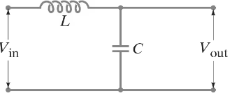
Filter circuit. Figure 30–33 shows a simple filter circuit designed to pass dc voltages with minimal attenuation and to remove, as much as possible, any ac components (such as 60-Hz line voltage that could cause hum in an audio system, for example). Assume Vin = V1 + V2 where V1 is dc and V2 = V20 sin ωt, and that any resistance is very small. (a) Determine the current through the capacitor: give amplitude and phase (assume R = 0 and XL > XC). (b) Show that the ac component of the output voltage, V2out, equals (Q/C) - V1 where Q is the charge on the capacitor at any instant, and determine the amplitude and phase of V2out (c) Show that the attenuation of the ac voltage is greatest when XC << XL, and calculate the ratio of the output to input ac voltage in this case. (d) Compare the dc output voltage to input voltage.

Verified step by step guidance
1
Step 1: Analyze the given circuit and understand the components. The circuit consists of a capacitor and an inductor, and the input voltage is given as Vᵢₙ = V₁ + V₂, where V₁ is the DC component and V₂ = V₂₀ sin(ωt) is the AC component. The goal is to analyze the behavior of the circuit for both AC and DC components.
Step 2: (a) To determine the current through the capacitor, use the relationship for capacitive reactance: X_C = 1 / (ωC), where ω is the angular frequency and C is the capacitance. The current through the capacitor is given by I_C = V₂ / X_C. Since V₂ = V₂₀ sin(ωt), the amplitude of the current is I_C₀ = V₂₀ / X_C, and the phase difference between the voltage and current is -π/2 (current leads voltage in a capacitor).
Step 3: (b) To show that the AC component of the output voltage V₂ₒᵤₜ equals (Q/C) - V₁, recall that the voltage across a capacitor is related to the charge by V_C = Q / C. The AC component of the output voltage is the voltage across the capacitor due to the AC charge Q_AC. Since V₁ is the DC component, subtracting it isolates the AC component. The amplitude of V₂ₒᵤₜ is determined by the amplitude of Q_AC, and the phase is the same as the phase of Q_AC.
Step 4: (c) To show that the attenuation of the AC voltage is greatest when X_C << X_L, note that the inductor's reactance X_L = ωL increases with frequency, while the capacitor's reactance X_C decreases with frequency. When X_C << X_L, the capacitor dominates the circuit's impedance, and the AC voltage across the capacitor (output voltage) is significantly reduced compared to the input AC voltage. The ratio of the output to input AC voltage is given by |V₂ₒᵤₜ / V₂₀| = X_C / (X_C + X_L).
Step 5: (d) Compare the DC output voltage to the input voltage. Since the capacitor blocks DC current, the DC output voltage Vₒᵤₜ_DC is equal to the DC input voltage V₁. This is because the capacitor does not affect the steady-state DC component of the circuit, and the inductor does not impede DC current flow (its reactance is zero at DC).

Verified video answer for a similar problem:

This video solution was recommended by our tutors as helpful for the problem above.
Video duration:
12m
Was this helpful?

Key Concepts

Here are the essential concepts you must grasp in order to answer the question correctly.

Capacitive Reactance (XC)

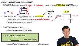
Capacitive reactance (XC) is the opposition that a capacitor offers to alternating current (AC) due to its capacitance. It is inversely proportional to the frequency of the AC signal and the capacitance value, given by the formula XC = 1/(2πfC). In filter circuits, understanding XC is crucial for determining how effectively the circuit can block AC components while allowing DC signals to pass.
Recommended video:
Guided course
08:02
Capacitors & Capacitance (Intro)

Charge on a Capacitor (Q)

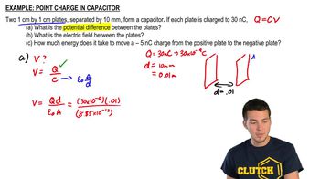
The charge (Q) on a capacitor is the amount of electric charge stored in it, which is directly proportional to the voltage (V) across its plates and its capacitance (C), expressed as Q = CV. In the context of the filter circuit, the charge on the capacitor influences the output voltage and the phase relationship between the input and output signals, particularly when analyzing AC components.
Recommended video:
Guided course
06:07
Point Charge Inside Capacitor

Voltage Attenuation

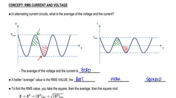
Voltage attenuation refers to the reduction in amplitude of a signal as it passes through a circuit. In filter circuits, attenuation is particularly relevant for AC signals, where the relationship between capacitive reactance (XC) and inductive reactance (XL) determines how much of the AC voltage is allowed to pass. When XC is much smaller than XL, the attenuation of the AC voltage is maximized, leading to a significant drop in the output AC voltage compared to the input.
Recommended video:
Guided course
07:14
RMS Current and Voltage
Related Practice
Textbook Question

In some experiments, very tiny distances or spaces ( ≈ nm ) can be measured by using capacitance. Consider forming an LC circuit using a parallel-plate capacitor with plate area A, and a known inductance L. If f is on the order of 1 MHz and can be measured to a precision of ∆f = 1 Hz, with what percent accuracy can x be determined? Assume fringing effects at the capacitor’s edges can be neglected.

830
views
Textbook Question

In some experiments, very tiny distances or spaces ( ≈ nm ) can be measured by using capacitance. Consider forming an LC circuit using a parallel-plate capacitor with plate area A, and a known inductance L. If charge is found to oscillate in this circuit at frequency f = ω/2π when the capacitor plates are separated by distance x, show that x = 4π² Aε₀f²L.

1008
views
Textbook Question

Show that if the inductor L in the filter circuit of Fig. 30–33 (Problem 87) is replaced by a large resistor R, there will still be significant attenuation of the ac voltage and little attenuation of the dc voltage if the input dc voltage is high and the current (and power) are low.

1511
views
Textbook Question

In some experiments, very tiny distances or spaces ( ≈ nm ) can be measured by using capacitance. Consider forming an LC circuit using a parallel-plate capacitor with plate area A, and a known inductance L. When the plate separation is changed by ∆x, the circuit’s oscillation frequency will change by ∆f. Show that ∆x/x ≈ 2(∆f/f).

883
views
Textbook Question

For the circuit shown in Fig. 30–35, show that if the condition R₁ R₂ = L/C is satisfied then the potential difference between points a and b is zero for all frequencies.

1068
views
Textbook Question

Suppose a series LRC circuit has two resistors, R₁ and R₂, two capacitors, C₁ and C₂, and two inductors, L₁ and L₂ all in series. Calculate the total impedance of the circuit.

1507
views