
Ch. 30 - Inductance, Electromagnetic Oscillations, and AC Circuits
Giancoli Douglas - Physics for Scientists and Engineers 5th edition
Giancoli Douglas5th editionPhysics for Scientists and EngineersISBN: 9780137488179Not the one you use?Change textbook
Chapter 29, Problem 66

Show that the power delivered by a three-phase ac source equals a constant P = 3Vo²/2R, by combining the four equations in Section 30–11.

Verified step by step guidance
1
Start by recalling the key equations for a three-phase AC source. Each phase delivers a voltage described by \( V(t) = V_0 \sin(\omega t + \phi) \), where \( V_0 \) is the peak voltage, \( \omega \) is the angular frequency, and \( \phi \) is the phase angle. For a balanced three-phase system, the phase angles are separated by \( 120^\circ \) (or \( 2\pi/3 \) radians).
The instantaneous power delivered by one phase is given by \( P(t) = \frac{V^2(t)}{R} \), where \( R \) is the resistance of the load. Substituting \( V(t) = V_0 \sin(\omega t + \phi) \), we get \( P(t) = \frac{V_0^2 \sin^2(\omega t + \phi)}{R} \).
For a three-phase system, the total instantaneous power is the sum of the powers from all three phases. Using the phase angles \( \phi_1 = 0 \), \( \phi_2 = -120^\circ \), and \( \phi_3 = -240^\circ \), the total power is \( P_{\text{total}}(t) = \frac{V_0^2}{R} [\sin^2(\omega t) + \sin^2(\omega t - 120^\circ) + \sin^2(\omega t - 240^\circ)] \).
Use the trigonometric identity \( \sin^2(x) = \frac{1 - \cos(2x)}{2} \) to simplify each term. After simplification, the cosine terms cancel out due to symmetry, leaving \( P_{\text{total}}(t) = \frac{3V_0^2}{2R} \).
Conclude that the total power delivered by the three-phase AC source is constant and equals \( P = \frac{3V_0^2}{2R} \), as the time-dependent terms have been eliminated through the summation of the three phases.

Verified video answer for a similar problem:

This video solution was recommended by our tutors as helpful for the problem above.
Video duration:
8m
Was this helpful?

Key Concepts

Here are the essential concepts you must grasp in order to answer the question correctly.

Three-Phase AC Power

Three-phase AC power systems use three alternating currents that are offset in phase by 120 degrees. This configuration allows for a more efficient power delivery compared to single-phase systems, as it provides a constant power transfer and reduces the amount of conductor material needed. The total power in a three-phase system can be calculated using the formula P = √3 × V_L × I_L, where V_L is the line voltage and I_L is the line current.
Recommended video:
Guided course
05:37
Power in AC Circuits

Voltage and Resistance Relationship

In electrical circuits, the relationship between voltage (V), current (I), and resistance (R) is described by Ohm's Law, which states V = I × R. This fundamental principle allows us to understand how voltage drops across resistors and how it affects the current flow in the circuit. In the context of power calculations, the power dissipated in a resistor can be expressed as P = V²/R, highlighting the importance of both voltage and resistance in determining power.
Recommended video:
Guided course
07:14
RMS Current and Voltage

Power Calculation in AC Circuits

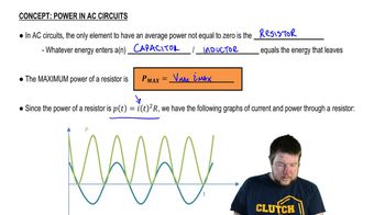
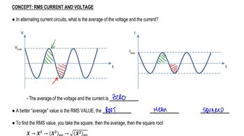
The power delivered by an AC source can be calculated using the root mean square (RMS) values of voltage and current. For a resistive load, the average power can be expressed as P = I_RMS² × R or P = V_RMS²/R. In three-phase systems, the total power is the sum of the power in each phase, leading to the formula P = 3V_o²/2R when considering the phase voltage and the resistive load, which is derived from the combination of the relevant equations.
Recommended video:
Guided course
05:37
Power in AC Circuits
Related Practice
Textbook Question

The frequency of the ac voltage source (peak voltage Vo) in an LRC circuit is tuned to the circuit’s resonant frequency f₀ = 1 / (2π√LC). (a) Show that the peak voltage across the capacitor is Vco = VoTo/ (2πτ), where To ( =1/fo) is the period of the resonant frequency and τ = RC is the time constant for charging the capacitor C through a resistor R. (b) Define β = To/ (2πτ) so that Vco = βVo. Then β is the “amplification” of the source voltage across the capacitor. If a particular LRC circuit contains a 2.0-nF capacitor and has a resonant frequency of 5.0 kHz, what value of R will yield β = 125?

1375
views
Textbook Question

(II) (a) Show that oscillation of charge Q on the capacitor of an LRC circuit has amplitude


Q0=V0(ωR)2+(ω2L1C)2.Q_0 = \(\frac{V_0}{\sqrt{(\omega R)^2 + \left(\omega^2 L - \frac{1}{C}\]\right\))^2}}.

1523
views
Textbook Question

At t = 0, the current through a 60.0-mH inductor is 50.0 mA and is increasing at the rate of 78.0 mA/s. What is the initial energy stored in the inductor, and how long does it take for the energy to increase by a factor of 8.0 from the initial value?

1008
views
Textbook Question

The output of an electrocardiogram amplifier has an impedance of 45 Ω. It is to be connected to an 8.0-Ω loudspeaker through a transformer. What should be the turns ratio of the transformer?

1070
views
Textbook Question

At time t = 0, the switch in the circuit shown in Fig. 30–30 is closed. After a sufficiently long time, steady currents I₁, I₂, and I₃ flow through resistors R₁, R₂, and R₃, respectively. Determine these three currents.

973
views
Textbook Question

A pair of straight parallel thin wires, such as a lamp cord, each of radius r, are a distance 𝓁 apart and carry current to a circuit some distance away. Ignoring the field within each wire, show that the inductance per unit length is (μ₀/π) ln[(𝓁 - r) /r].

1577
views