
Ch 30: Electromagnetic Induction
Knight Calc - Physics for Scientists and Engineers 5th Edition
Knight Calc5th EditionPhysics for Scientists and EngineersISBN: 9780137344796Not the one you use?Change textbook
Chapter 30, Problem 81

CALC The rectangular loop in FIGURE CP30.81 has 0.020 Ω resistance. What is the induced current in the loop at this instant?

Verified step by step guidance
1
Identify the key components of the problem: The rectangular loop has a resistance of 0.020 Ω, and we need to calculate the induced current. The induced current is related to the change in magnetic flux through the loop, as described by Faraday's Law of Induction.
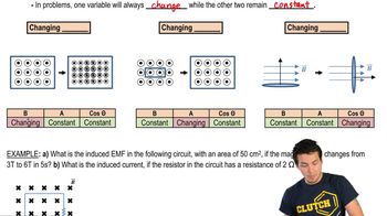
Apply Faraday's Law of Induction, which states that the induced electromotive force (EMF) is given by: ε=−dΦmdt, where Φm is the magnetic flux through the loop.
Calculate the magnetic flux Φm using the formula: Φm=BAcosθ, where B is the magnetic field strength, A is the area of the loop, and θ is the angle between the magnetic field and the normal to the loop. Determine how Φm changes with time.
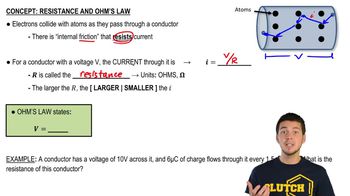
Relate the induced EMF to the induced current using Ohm's Law: I=εR, where I is the induced current, ε is the induced EMF, and R is the resistance of the loop (0.020 Ω in this case).
Substitute the values for ε (calculated from Faraday's Law) and R into the formula for I to find the induced current. Ensure all units are consistent during the calculation.

Verified video answer for a similar problem:

This video solution was recommended by our tutors as helpful for the problem above.
Was this helpful?

Key Concepts

Here are the essential concepts you must grasp in order to answer the question correctly.

Faraday's Law of Electromagnetic Induction

Faraday's Law states that a change in magnetic flux through a loop induces an electromotive force (EMF) in the loop. The induced EMF is proportional to the rate of change of the magnetic flux, which can be caused by moving a magnet towards or away from the loop or changing the magnetic field strength. This principle is fundamental for understanding how currents are generated in conductive loops.
Recommended video:
Guided course
09:26
Faraday's Law

Ohm's Law

Ohm's Law relates the voltage (V), current (I), and resistance (R) in an electrical circuit, expressed as V = IR. In the context of the induced current in the loop, the induced EMF acts as the voltage, and the resistance of the loop determines how much current flows. This relationship is crucial for calculating the induced current once the EMF is known.
Recommended video:
Guided course
03:07
Resistance and Ohm's Law

Induced Current

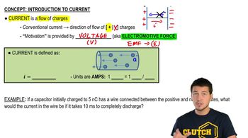
Induced current is the electric current generated in a conductor due to a changing magnetic field, as described by Faraday's Law. The direction of the induced current is given by Lenz's Law, which states that it will flow in a direction that opposes the change in magnetic flux that produced it. Understanding this concept is essential for predicting the behavior of the current in the loop when subjected to varying magnetic conditions.
Recommended video:
Guided course
05:38
Intro to Current
Related Practice
Textbook Question

CALC Let's look at the details of eddy-current braking. A square loop, length l on each side, is shot with velocity v0 into a uniform magnetic field B. The field is perpendicular to the plane of the loop. The loop has mass m and resistance R, and it enters the field at t = 0 s. Assume that the loop is moving to the right along the x-axis and that the field begins at x = 0 m. Find an expression for the loop's velocity as a function of time as it enters the magnetic field. You can ignore gravity, and you can assume that the back edge of the loop has not entered the field.

77
views
Textbook Question

CALC High-frequency signals are often transmitted along a coaxial cable, such as the one shown in FIGURE CP30.86. For example, the cable TV hookup coming into your home is a coaxial cable. The signal is carried on a wire of radius r1 while the outer conductor of radius r2 is grounded. A soft, flexible insulating material fills the space between them, and an insulating plastic coating goes around the outside. Evaluate the inductance per meter of a cable having r1 = 0.50 mm and r2 = 3.0 mm.

188
views
Textbook Question

The switch in FIGURE P30.77 has been open for a long time. It is closed at t = 0 s. After the switch has been closed for a long time, what is the current in the circuit? Call this current I0.

94
views
Textbook Question

CALC Let's look at the details of eddy-current braking. A square loop, length l on each side, is shot with velocity v0 into a uniform magnetic field B. The field is perpendicular to the plane of the loop. The loop has mass m and resistance R, and it enters the field at t=0 s. Assume that the loop is moving to the right along the x-axis and that the field begins at x = 0 m. Calculate and draw a graph of v over the interval 0 s ≤ t ≤ 0.04 s for the case that v0=10 m/s, l = 10 cm, m = 1.0 g, R = 0.0010 Ω, and B=0.10 T. The back edge of the loop does not reach the field during this time interval.

45
views
Textbook Question

In recent years it has been possible to buy a 1.0 F capacitor. This is an enormously large amount of capacitance. Suppose you want to build a 1.0 Hz oscillator with a 1.0 F capacitor. You have a spool of 0.25-mm-diameter wire and a 4.0-cm-diameter plastic cylinder. How long must your inductor be if you wrap it with 2 layers of closely spaced turns?

1290
views
Textbook Question

The switch in FIGURE P30.77 has been open for a long time. It is closed at t = 0 s. Find an expression for the current I as a function of time. Write your expression in terms of I0, R, and L.

77
views