
Ch 28: Fundamentals of Circuits
Knight Calc - Physics for Scientists and Engineers 5th Edition
Knight Calc5th EditionPhysics for Scientists and EngineersISBN: 9780137344796Not the one you use?Change textbook
Chapter 28, Problem 66

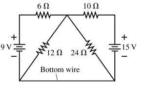
How much current flows through the bottom wire in FIGURE P28.66, and in which direction?

Verified step by step guidance
1
Step 1: Analyze the circuit configuration. The circuit consists of two voltage sources (9 V and 15 V) and resistors arranged in a combination of series and parallel connections. The bottom wire connects the 12 Ω and 24 Ω resistors in the triangular section of the circuit.
Step 2: Apply Kirchhoff's Voltage Law (KVL) to the loops in the circuit. KVL states that the sum of the potential differences (voltage drops and rises) around any closed loop is zero. Identify the two main loops: one containing the 9 V battery and the 6 Ω resistor, and the other containing the 15 V battery and the 10 Ω resistor.
Step 3: Calculate the equivalent resistance of the triangular section. The 12 Ω and 24 Ω resistors are connected in parallel. Use the formula for parallel resistance: Req=1112+124. Simplify to find the equivalent resistance.
Step 4: Determine the current in each loop using Ohm's Law (I=VR). For each loop, calculate the total resistance and use the voltage of the respective battery to find the current.
Step 5: Use Kirchhoff's Current Law (KCL) at the junctions to find the current through the bottom wire. KCL states that the sum of currents entering a junction equals the sum of currents leaving the junction. Combine the currents from the two loops and determine the direction of the current through the bottom wire based on the net flow.

Verified video answer for a similar problem:

This video solution was recommended by our tutors as helpful for the problem above.
Was this helpful?

Key Concepts

Here are the essential concepts you must grasp in order to answer the question correctly.

Ohm's Law

Ohm's Law states that the current (I) flowing through a conductor between two points is directly proportional to the voltage (V) across the two points and inversely proportional to the resistance (R) of the conductor. This relationship is expressed mathematically as I = V/R. Understanding this law is crucial for calculating the current in the circuit based on the voltage sources and resistances present.
Recommended video:
Guided course
03:07
Resistance and Ohm's Law

Series and Parallel Circuits

In electrical circuits, components can be arranged in series or parallel configurations. In a series circuit, the current is the same through all components, while the total resistance is the sum of individual resistances. In a parallel circuit, the voltage across each component is the same, and the total current is the sum of the currents through each branch. Recognizing the arrangement of resistors in the given circuit is essential for determining the current through the bottom wire.
Recommended video:
Guided course
09:51
Combining Capacitors in Series & Parallel

Kirchhoff's Laws

Kirchhoff's Laws consist of two principles that govern the conservation of charge and energy in electrical circuits. Kirchhoff's Current Law (KCL) states that the total current entering a junction must equal the total current leaving it, while Kirchhoff's Voltage Law (KVL) states that the sum of the electrical potential differences around any closed circuit loop must equal zero. These laws are fundamental for analyzing complex circuits and finding unknown currents and voltages.
Recommended video:
Guided course
04:08
Kirchhoff's Junction Rule
Related Practice
Textbook Question

A 12 V car battery dies not so much because its voltage drops but because chemical reactions increase its internal resistance. A good battery connected with jumper cables can both start the engine and recharge the dead battery. Consider the automotive circuit of FIGURE P28.64. How much current is the dead battery alone able to drive through the starter motor?

1729
views
Textbook Question

The capacitor in an RC circuit is discharged with a time constant of 10 ms. At what time after the discharge begins are (a) the charge on the capacitor reduced to half its initial value and (b) the energy stored in the capacitor reduced to half its initial value?

150
views
Textbook Question

What is the current through the 10 Ω resistor in FIGURE P28.61? Is the current from left to right or right to left?

232
views
Textbook Question

A circuit you're building needs an ammeter that goes from 0 mA to a full-scale reading of 50 mA. Unfortunately, the only ammeter in the storeroom goes from 0 μA to a full-scale reading of only 500 μA. Fortunately, you've just finished a physics class, and you realize that you can make this ammeter work by putting a resistor in parallel with it, as shown in FIGURE P28.56. You've measured that the resistance of the ammeter is 50.0 Ω, not the 0 Ω of an ideal ammeter. What is the effective resistance of your ammeter?

63
views
Textbook Question

A 150 μF defibrillator capacitor is charged to 1500 V. When fired through a patient’s chest, it loses 95% of its charge in 40 ms. What is the resistance of the patient’s chest?

62
views
Textbook Question

A circuit you’re using discharges a 20 μF capacitor through an unknown resistor. After charging the capacitor, you close a switch at t = 0 s and then monitor the resistor current with an ammeter. Your data are as follows: Use an appropriate graph of the data to determine (a) the resistance and (b) the initial capacitor voltage.

72
views