
Ch 32: AC Circuits
Knight Calc - Physics for Scientists and Engineers 5th Edition
Knight Calc5th EditionPhysics for Scientists and EngineersISBN: 9780137344796Not the one you use?Change textbook
Chapter 32, Problem 63a

Commercial electricity is generated and transmitted as three-phase electricity. Instead of a single emf, three separate wires carry currents for the emfs ε1 = ε0 cos ωt, ε2 = ε0 cos(ωt +120°), and ε3 = ε0 cos(ωt−120°) over three parallel wires, each of which supplies one-third of the power. This is why the long-distance transmission lines you see in the countryside have three wires. Suppose the transmission lines into a city supply a total of 450 MW of electric power, a realistic value. What would be the rms current in each wire if the transmission voltage were ε0 = 120 V rms?

Verified step by step guidance
1
Step 1: Understand the problem. The total power supplied by the three-phase system is given as 450 MW, and the rms voltage for each wire is ε₀ = 120 V rms. We need to calculate the rms current in each wire. Recall that in a three-phase system, the total power is distributed equally among the three wires.
Step 2: Recall the formula for power in an AC circuit: P = V_rms × I_rms × cos(ϕ), where P is the power, V_rms is the rms voltage, I_rms is the rms current, and cos(ϕ) is the power factor. For simplicity, assume the power factor cos(ϕ) = 1 (ideal case).
Step 3: Divide the total power among the three wires. Since the power is equally distributed, the power per wire is P_wire = Total Power / 3. Substitute the given total power (450 MW) into this formula to find the power per wire.
Step 4: Rearrange the power formula to solve for I_rms. Using P_wire = V_rms × I_rms × cos(ϕ), isolate I_rms: I_rms = P_wire / (V_rms × cos(ϕ)). Substitute the values for P_wire, V_rms, and cos(ϕ) into this formula.
Step 5: Perform the substitution and simplify the expression to find the rms current in each wire. Ensure the units are consistent (e.g., convert MW to W if necessary).

Verified video answer for a similar problem:

This video solution was recommended by our tutors as helpful for the problem above.
Video duration:
3m
Was this helpful?

Key Concepts

Here are the essential concepts you must grasp in order to answer the question correctly.

Three-Phase Electricity

Three-phase electricity is a method of alternating current (AC) power generation and transmission that uses three separate conductors, each carrying a current that is phase-shifted by 120 degrees. This configuration allows for a more efficient and stable power supply, as the total power delivered is constant, reducing fluctuations and improving the overall efficiency of the system.
Recommended video:
Guided course
08:59
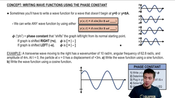
Phase Constant of a Wave Function

RMS Voltage and Current

RMS (Root Mean Square) voltage and current are measures used to express the effective value of alternating currents and voltages. The RMS value is equivalent to a direct current (DC) value that would deliver the same power to a load. For example, an RMS voltage of 120 V means that it can deliver the same power as a 120 V DC source, making it crucial for calculating power in AC circuits.
Recommended video:
Guided course
07:14
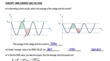
RMS Current and Voltage

Power Calculation in AC Circuits

In AC circuits, the total power can be calculated using the formula P = √3 × V_rms × I_rms, where P is the total power, V_rms is the RMS voltage, and I_rms is the RMS current. For three-phase systems, the power is distributed equally among the three phases, allowing for the calculation of the current in each wire when the total power and voltage are known.
Recommended video:
Guided course
05:37
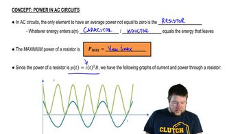
Power in AC Circuits
Related Practice
Textbook Question

A television channel is assigned the frequency range from 54 MHz to 60 MHz. A series RLC tuning circuit in a TV receiver resonates in the middle of this frequency range. The circuit uses a 16 pF capacitor. What is the value of the inductor?

1860
views
Textbook Question

The tuning circuit in an FM radio receiver is a series RLC circuit with a 0.200 μH inductor. The receiver is tuned to a station at 104.3 MHz. What is the value of the capacitor in the tuning circuit?

136
views
Textbook Question

The tuning circuit in an FM radio receiver is a series RLC circuit with a 0.200 μH inductor. FM radio stations are assigned frequencies every 0.2 MHz, but two nearby stations cannot use adjacent frequencies. What is the maximum resistance the tuning circuit can have if the peak current at a frequency of 103.9 MHz, the closest frequency that can be used by a nearby station, is to be no more than 0.10% of the peak current at 104.3 MHz? The radio is still tuned to 104.3 MHz, and you can assume the two stations have equal strength.

1948
views
Textbook Question

A generator consists of a 12-cm by 16-cm rectangular loop with 500 turns of wire spinning at 60 Hz in a 25 mT uniform magnetic field. The generator output is connected to a series RC circuit consisting of a 120 Ω resistor and a 35 μF capacitor. What is the average power delivered to the circuit?

1425
views
Textbook Question

You're the operator of a 15,000 V rms, 60 Hz electrical substation. When you get to work one day, you see that the station is delivering 6.0 MW of power with a power factor of 0.90. What is the rms current leaving the station?

144
views
Textbook Question

Commercial electricity is generated and transmitted as three-phase electricity. Instead of a single emf, three separate wires carry currents for the emfs ε1 = ε0 cos ωt, ε2 = ε0 cos(ωt +120°), and ε3 = ε0 cos(ωt−120°) over three parallel wires, each of which supplies one-third of the power. This is why the long-distance transmission lines you see in the countryside have three wires. Suppose the transmission lines into a city supply a total of 450 MW of electric power, a realistic value. In fact, transformers are used to step the transmission-line voltage up to 500 kV rms. What is the current in each wire?

1690
views