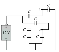
Ch 26: Potential and Field
Knight Calc - Physics for Scientists and Engineers 5th Edition
Knight Calc5th EditionPhysics for Scientists and EngineersISBN: 9780137344796Not the one you use?Change textbook
Chapter 26, Problem 59b

Six identical capacitors with capacitance C are connected as shown in FIGURE P26.59. What is the potential difference between points a and b?
Diagram of six identical capacitors connected in a circuit with a 12V battery, showing points a and b for potential difference measurement.

Verified step by step guidance
1
Step 1: Analyze the circuit configuration. The six capacitors are arranged in a combination of series and parallel connections. Identify the groups of capacitors that are in series and parallel relative to points a and b.
Step 2: Simplify the circuit step by step. Start by combining the capacitors that are in series or parallel. For capacitors in series, the equivalent capacitance is given by: 1C = 1C + 1C + .... For capacitors in parallel, the equivalent capacitance is given by: Ceq = C1 + C2 + ....
Step 3: Combine the two capacitors connected in series between points a and b. Use the formula for series capacitance to find their equivalent capacitance.
Step 4: Combine the equivalent capacitance from Step 3 with the capacitor in parallel to it. Use the formula for parallel capacitance to find the new equivalent capacitance.
Step 5: Calculate the potential difference between points a and b using the relationship between charge, capacitance, and voltage: V = QC. Use the total voltage supplied by the battery and the equivalent capacitance of the circuit to determine the voltage across the relevant capacitors.

Verified video answer for a similar problem:

This video solution was recommended by our tutors as helpful for the problem above.
Was this helpful?

Key Concepts

Here are the essential concepts you must grasp in order to answer the question correctly.

Capacitance

Capacitance is the ability of a capacitor to store charge per unit voltage. It is measured in farads (F) and is defined as C = Q/V, where Q is the charge stored and V is the voltage across the capacitor. In this problem, understanding the capacitance of the individual capacitors is crucial for calculating the total capacitance of the circuit configuration.
Recommended video:
Guided course
08:02
Capacitors & Capacitance (Intro)

Series and Parallel Connections

Capacitors can be connected in series or parallel, affecting the total capacitance. In series, the total capacitance (C_total) is given by 1/C_total = 1/C1 + 1/C2 + ... for each capacitor. In parallel, the total capacitance is the sum of individual capacitances: C_total = C1 + C2 + .... Recognizing how the capacitors in the circuit are arranged is essential for determining the potential difference between points a and b.
Recommended video:
Guided course
09:51
Combining Capacitors in Series & Parallel

Voltage Division

Voltage division is the principle that the voltage across components in a series circuit is divided among them based on their resistances or capacitances. In the context of capacitors, the voltage across each capacitor in series is proportional to its capacitance. Understanding how voltage is distributed in the circuit will help in calculating the potential difference between points a and b.
Recommended video:
Guided course
07:14
RMS Current and Voltage