

Ch 30: Electromagnetic Induction
Knight Calc - Physics for Scientists and Engineers 5th Edition
Knight Calc5th EditionPhysics for Scientists and EngineersISBN: 9780137344796Not the one you use?Change textbook
Chapter 30, Problem 47

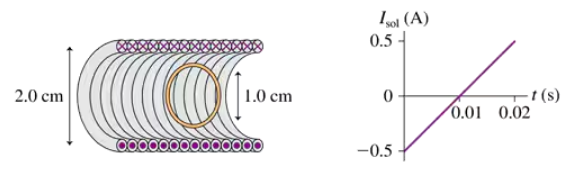
FIGURE P30.47 shows a 1.0-cm-diameter loop with R = 0.50 Ω inside a 2.0-cm-diameter solenoid. The solenoid is 8.0 cm long, has 120 turns, and carries the current shown in the graph. A positive current is cw when seen from the left. Determine the current in the loop at t = 0.010 s.

Verified step by step guidance
1
Step 1: Understand the setup. The solenoid has a diameter of 2.0 cm, a length of 8.0 cm, and 120 turns. The loop inside the solenoid has a diameter of 1.0 cm and a resistance of 0.50 Ω. The graph shows the current in the solenoid, which varies linearly with time. At t = 0.010 s, the solenoid current is 0 A, and its rate of change can be determined from the slope of the graph.
Step 2: Calculate the magnetic field inside the solenoid. The magnetic field inside a solenoid is given by the formula: B=μnIL, where μ is the permeability of free space, n is the number of turns per unit length, and I is the current in the solenoid. First, calculate n as n=1200.08 turns per meter.
Step 3: Determine the rate of change of the magnetic field. The graph shows that the solenoid current changes linearly with time. The slope of the graph gives the rate of change of current, dIdt. Use this slope to calculate the rate of change of the magnetic field, dBdt, using the formula: dBdt=μndIdt.
Step 4: Calculate the induced emf in the loop. The induced emf is given by Faraday's law: ε=-dt, where Φ is the magnetic flux. The flux through the loop is Φ=BA, where A is the area of the loop. Use the formula for the area of a circle, A=πr², to calculate the area of the loop, and substitute dBdt to find ε.
Step 5: Determine the current in the loop. The induced current in the loop is given by Ohm's law: I=εR, where R is the resistance of the loop. Substitute the value of ε and R to calculate the current in the loop at t=0.010 s.

Verified video answer for a similar problem:

This video solution was recommended by our tutors as helpful for the problem above.
Was this helpful?

Key Concepts

Here are the essential concepts you must grasp in order to answer the question correctly.

Electromagnetic Induction

Electromagnetic induction is the process by which a changing magnetic field within a closed loop induces an electromotive force (EMF) in that loop. This phenomenon is described by Faraday's Law, which states that the induced EMF is proportional to the rate of change of magnetic flux through the loop. In this scenario, the current in the solenoid creates a magnetic field that changes over time, inducing a current in the loop.
Recommended video:
Guided course
05:42
Introduction to Induction

Ohm's Law

Ohm's Law relates the voltage (V), current (I), and resistance (R) in an electrical circuit, expressed as V = IR. In the context of the loop, once the induced EMF is calculated, Ohm's Law can be used to determine the current flowing through the loop by dividing the induced EMF by the resistance of the loop. This relationship is crucial for solving the problem as it connects the induced voltage to the resulting current.
Recommended video:
Guided course
03:07
Resistance and Ohm's Law

Magnetic Flux

Magnetic flux is a measure of the quantity of magnetism, taking into account the strength and the extent of a magnetic field. It is defined as the product of the magnetic field (B) and the area (A) through which the field lines pass, and is given by the equation Φ = B·A·cos(θ), where θ is the angle between the magnetic field lines and the normal to the surface. Understanding magnetic flux is essential for determining how the changing magnetic field from the solenoid affects the loop.
Recommended video:
Guided course
04:52
Magnetic Flux
Related Practice
Textbook Question

A 2.0 cm×2.0 cm square loop of wire with resistance 0.010 Ω has one edge parallel to a long straight wire. The near edge of the loop is 1.0 cm from the wire. The current in the wire is increasing at the rate of 100 A/s. What is the current in the loop?

153
views
Textbook Question

CALC An electric generator has an 18-cm-diameter, 120-turn coil that rotates at 60 Hz in a uniform magnetic field that is perpendicular to the rotation axis. What magnetic field strength is needed to generate a peak voltage of 170 V?

150
views
Textbook Question

CALC A 10 cm×10 cm square loop of wire lies in the xy-plane. The magnetic field in this region of space is B=(0.30ti^+0.50t2k^) T\(\vec{B}\) = (0.30t\(\hat{i}\) + 0.50t^2\(\hat{k}\))\(\text{ T}\), where t is in s. What is the emf induced in the loop at (a) t = 0.5 s and (b) t = 1.0 s?

87
views
Textbook Question

A small, 2.0-mm-diameter circular loop with R = 0.020 Ω is at the center of a large 100-mm-diameter circular loop. Both loops lie in the same plane. The current in the outer loop changes from +1.0 A to −1.0 A in 0.10 s. What is the induced current in the inner loop?

69
views
Textbook Question

CALC An 8.0 cm×8.0 cm square loop is halfway into a magnetic field perpendicular to the plane of the loop. The loop's mass is 10 g and its resistance is 0.010 Ω. A switch is closed at t = 0 s, causing the magnetic field to increase from 0 to 1.0 T in 0.010 s. Hint: What is the impulse on the loop? With what speed is the loop 'kicked' away from the magnetic field?

175
views
Textbook Question

FIGURE P30.48 shows two 20-turn coils tightly wrapped on the same 2.0-cm-diameter cylinder with 1.0-mm-diameter wire. The current through coil 1 is shown in the graph. Determine the current in coil 2 at (a) t = 0.05 s and (b) t = 0.25 s. A positive current is into the figure at the top of a loop. Assume that the magnetic field of coil 1 passes entirely through coil 2.

1771
views