
Consider two unequal resistors, of resistance R1 and R2, that are connected either in series or in parallel. Fill in the Table below assuming the electric potential on the low-voltage end of the combination is VA volts and the potential at the high-voltage end of the combination is VB volts. First draw diagrams.
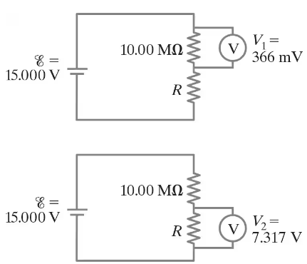
Measurements made on circuits that contain large resistances can be confusing. Consider a circuit powered by a battery ε = 15.000 V with a 10.00-MΩ resistor in series with an unknown resistor R. As shown in Fig. 26–92, a particular voltmeter reads V1 = 366 mV when connected across the 10.00 -MΩ resistor and this meter reads V2 = 7.317 V when connected across R. Determine the value of R. [Hint: Define RV as the voltmeter’s internal resistance.]

Verified step by step guidance
Verified video answer for a similar problem:
Key Concepts
Ohm's Law
Voltage Divider Rule
Internal Resistance of a Voltmeter
In the circuit shown in Fig. 26–75, the 33-Ω resistor dissipates 0.80 W. What is the battery voltage?
The circuit shown in Fig. 26–89 is a primitive 4-bit digital-to-analog converter (DAC). In this circuit, to represent each digit (2n) of a binary number, a “1” has the nᵗʰ switch closed whereas zero (“0”) has the switch open. For example, 0010 is represented by closing switch n = 1, while all other switches are open. Show that the voltage V across the 1.0 - Ω resistor for the binary numbers 0001, 0010, 0100, and 1010 (which represent 1, 2, 4, 10) follows the pattern that you expect for a 4-bit DAC.
The performance of the starter circuit in a car can be significantly degraded by a small amount of corrosion on a battery terminal. Figure 26–88a depicts a properly functioning circuit with a battery (12.5-V emf, 0.02-Ω internal resistance) attached via corrosion-free cables to a starter motor of resistance Rs = 0.15Ω. Sometime later, corrosion between a battery terminal and a starter cable introduces an extra series resistance of only RC = 0.10Ω into the circuit as suggested in Fig. 26–88b. Let P0 be the power delivered to the starter in the circuit free of corrosion, and let P be the power delivered to the starter with corrosion. Determine the ratio P/P0.
