Ch. 30 - Inductance, Electromagnetic Oscillations, and AC Circuits
Giancoli Douglas - Physics for Scientists and Engineers 5th edition
Giancoli Douglas5th editionPhysics for Scientists and EngineersISBN: 9780137488179Not the one you use?Change textbook
Chapter 29, Problem 78

An ac voltage source V = Vo sin (ωt + 90°) is connected across an inductor L and current I = Io sin (ωt) flows in this circuit. Note that the current and source voltage are 90° out of phase.
(a) Directly calculate the average power delivered by the source over one period T of its sinusoidal cycle via the integral P = ∫₀ᵀ VI dt/T.
(b) Apply the relation P = Iᵣₘₛ Vᵣₘₛ cos Φ to this circuit and show that the answer you obtain is consistent with that found in part (a). Comment on your results.

Verified step by step guidance
1
Step 1: Start with part (a). The average power delivered by the source over one period T is given by the formula P = (1/T) ∫₀ᵀ V I dt. Substitute the expressions for V and I into this formula. V = V₀ sin(ωt + 90°) and I = I₀ sin(ωt).
Step 2: Simplify the product V * I. Using the trigonometric identity sin(A + 90°) = cos(A), rewrite V as V₀ cos(ωt). The product V * I then becomes V₀ I₀ cos(ωt) sin(ωt). Use the trigonometric identity 2 sin(A) cos(A) = sin(2A) to simplify this product further.
Step 3: The expression for V * I simplifies to (V₀ I₀ / 2) sin(2ωt). Substitute this into the integral for P. The integral becomes P = (1/T) ∫₀ᵀ (V₀ I₀ / 2) sin(2ωt) dt. Since sin(2ωt) is a sinusoidal function with a period T, its integral over one full period is zero. Therefore, the average power P = 0.
Step 4: Move to part (b). The formula P = Iᵣₘₛ Vᵣₘₛ cos(Φ) relates the average power to the root mean square (RMS) values of current and voltage, and the phase difference Φ between them. For an inductor, the phase difference Φ = 90°, so cos(Φ) = cos(90°) = 0. Substitute this into the formula to find P = Iᵣₘₛ Vᵣₘₛ cos(90°) = 0.
Step 5: Comment on the results. Both methods (direct integration and the RMS formula) yield the same result: the average power delivered by the source to the inductor is zero. This is consistent with the fact that in an ideal inductor, energy is alternately stored in the magnetic field and returned to the source, with no net energy dissipation over a full cycle.

Verified video answer for a similar problem:

This video solution was recommended by our tutors as helpful for the problem above.
Video duration:
4m
Was this helpful?

Key Concepts

Here are the essential concepts you must grasp in order to answer the question correctly.

Sinusoidal Functions

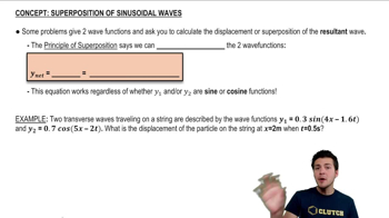
Sinusoidal functions, such as sine and cosine, describe periodic oscillations and are fundamental in analyzing AC circuits. In this context, the voltage and current are expressed as sinusoidal functions, indicating their time-varying nature. The phase difference between these functions, such as the 90° phase shift in this problem, is crucial for understanding how they interact in the circuit.
Recommended video:
Guided course
03:32
Superposition of Sinusoidal Wave Functions

Average Power in AC Circuits

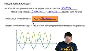
The average power delivered by an AC source can be calculated using the integral of the product of voltage and current over one complete cycle. This average power reflects the effective energy transfer in the circuit, accounting for the phase difference between voltage and current. The formula P = ∫₀ᵀ V I dt/T is used to compute this average power, which is essential for understanding energy consumption in AC systems.
Recommended video:
Guided course
05:37
Power in AC Circuits

Power Factor and RMS Values

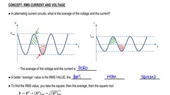
The power factor, represented as cos Φ, quantifies the efficiency of power usage in an AC circuit, where Φ is the phase angle between voltage and current. The root mean square (RMS) values of voltage and current are used to calculate the real power delivered to the load. The relation P = Iᵣₘₛ Vᵣₘₛ cos Φ connects these concepts, allowing for a consistent analysis of power in AC circuits, especially when phase differences are present.
Recommended video:
Guided course
07:14
RMS Current and Voltage
Related Practice
Textbook Question

An inductance coil draws 2.2 A dc when connected to a 45-V battery. When connected to a 60.0-Hz 120-V (rms) source, the current drawn is 3.8 A (rms). Determine the inductance and resistance of the coil.

1478
views

Textbook Question

In some experiments, very tiny distances or spaces ( ≈ nm ) can be measured by using capacitance. Consider forming an LC circuit using a parallel-plate capacitor with plate area A, and a known inductance L. If charge is found to oscillate in this circuit at frequency f = ω/2π when the capacitor plates are separated by distance x, show that x = 4π² Aε₀f²L.

1008
views
Textbook Question

At time t = 0, the switch in the circuit shown in Fig. 30–30 is closed. After a sufficiently long time, steady currents I₁, I₂, and I₃ flow through resistors R₁, R₂, and R₃, respectively. Determine these three currents.

973
views
Textbook Question

A pair of straight parallel thin wires, such as a lamp cord, each of radius r, are a distance 𝓁 apart and carry current to a circuit some distance away. Ignoring the field within each wire, show that the inductance per unit length is (μ₀/π) ln[(𝓁 - r) /r].

1577
views
Textbook Question

Show that the fraction of electromagnetic energy lost (to thermal energy) per cycle in a lightly damped (R² ≪ 4L/C) LRC circuit is approximately ΔUU=2πRLω=2πQ\(\frac{\Delta U}{U}\)=\(\frac{2\pi R}{L\omega}\)=\(\frac{2\pi}{Q}\). The quantity Q can be defined as Q = Lω/R, and is called the Q-value, or quality factor, of the circuit and is a measure of the damping present. A high Q-value means smaller damping and less energy input required to maintain oscillations.

1560
views
Textbook Question

For an underdamped LRC circuit, determine a formula for the energy U = UE + UB stored in the electric and magnetic fields as a function of time. Give answer in terms of the initial charge Qo on the capacitor.

1631
views