Capacitance is fundamentally defined as the ratio of the charge Q on a conductor to the potential difference V between two charged surfaces, expressed as C = Q / V. While calculating capacitance for parallel plate capacitors is straightforward due to their uniform electric field, more complex geometries like spherical or cylindrical capacitors require calculus to account for the varying electric field.
In a parallel plate capacitor, the electric field E is constant between the plates, so the potential difference is simply the product of the electric field and the distance between the plates, V = -E × d. However, for shapes such as concentric spheres, the electric field changes with distance because it depends on the enclosed charge and the geometry of the surfaces. This variation means the electric field is not uniform, and the potential difference must be calculated using the integral form:
\[ V = -\int_{A}^{B} \mathbf{E} \cdot d\mathbf{l} \]
where the integral is taken along the path from one surface to the other, and d𝑙 is the infinitesimal displacement vector. The dot product accounts for the component of the electric field along the path.
Consider the classic example of a spherical capacitor composed of two concentric spherical conducting shells with radii A (inner shell) and B (outer shell), carrying charges +Q and -Q respectively. The electric field between these shells behaves like that of a point charge and is radially directed. Its magnitude at a distance r from the center is given by Coulomb’s law:
\[ E(r) = \frac{kQ}{r^2} \hat{r} \]
where k is Coulomb’s constant, k = \(\frac{1}{4\pi \varepsilon_0}\), and 𝜀₀ is the permittivity of free space.
To find the potential difference between the shells, integrate the electric field from radius A to B:
\[ V_{AB} = -\int_{A}^{B} \mathbf{E} \cdot d\mathbf{l} = -\int_{A}^{B} \frac{kQ}{r^2} dr = kQ \left( \frac{1}{A} - \frac{1}{B} \right) \]
This integral accounts for the decreasing electric field strength as the distance from the charged shell increases. Substituting this potential difference back into the capacitance formula yields:
\[ C = \frac{Q}{V_{AB}} = \frac{Q}{kQ \left( \frac{1}{A} - \frac{1}{B} \right)} = \frac{1}{k} \frac{AB}{B - A} \]
Expressing k in terms of the permittivity of free space, the capacitance becomes:
\[ C = 4 \pi \varepsilon_0 \frac{AB}{B - A} \]
This formula elegantly captures how the capacitance depends on the radii of the spherical shells and the permittivity of the medium between them. It highlights that as the shells get closer (B approaches A), the capacitance increases, reflecting the stronger interaction between the charges.
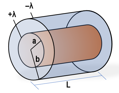
In summary, calculating capacitance for non-uniform electric fields involves integrating the electric field to find the potential difference, then applying the fundamental relation C = Q / V. This approach extends beyond spherical capacitors to other geometries like cylindrical capacitors, where the electric field similarly varies with position. Understanding these principles is essential for analyzing real-world capacitors with complex shapes and for designing devices with specific capacitance requirements.