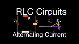
13:16RLC Circuits (12 of 19) Series RLC; Calculating Impedance, Current and VoltageStep by Step Science444
05:01RLC Circuits (3 of 19) Resistance; Phase Shift, Phasor Diagrams, Impedance, An ExplanationStep by Step Science123
Multiple Choice
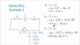
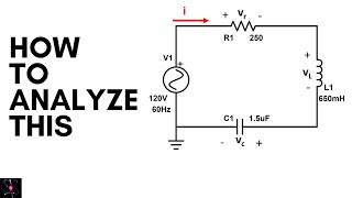
An AC source operates at an RMS voltage of 70 V and a frequency of 85 Hz. If the source is connected in series to a 20 Ω resistor, a 0.15 H inductor and a 500 µF capacitor, answer the following questions: a) What is the maximum current produced by the source? b) What is the maximum voltage across the resistor? c) What is the maximum voltage across the inductor? d) What is the maximum voltage across the capacitor?
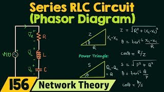
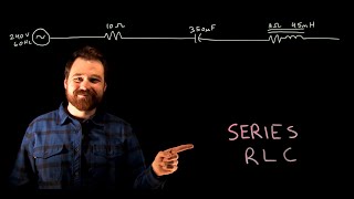
2851Has a video solution.
Multiple ChoiceAn inductor, a capacitor, and a resistor are in series with a 300Hz AC source. If the capacitor is 470nF, the inductor is 24mH, and the resistor is 800Ω, what is the impedance?104
Multiple ChoiceAn inductor, a capacitor, and a resistor are in series with a 300Hz AC source with peak voltage 13 V13V. If the impedance of the circuit is 3.4Ω, what is the peak current?103
Multiple ChoiceAn inductor, a capacitor, and a resistor are in series with an AC source. If the capacitor is 470 nF, the inductor is 24mH, and the resistor is 800 Ω800Ω, what is the circuit's resonant (angular) frequency?97
Multiple ChoiceAn inductor, a capacitor, and a resistor are in series with a 300Hz AC source. If the capacitor is 470 nF, the inductor is 24 mH, and the resistor is 800 Ω. what is the impedance?58
Multiple ChoiceAn inductor, a capacitor, and a resistor are in series with an AC source. If the capacitor is 470 nF, the inductor is 24 mH, and the resistor is 800 Ω. what is the circuit's resonant frequency?81
Textbook QuestionA series RLC circuit consists of a 75 Ω resistor, a 0.12 H inductor, and a 30 μF capacitor. It is attached to a 120 V/60 Hz power line. What are (a) the peak current I,
Textbook QuestionThe tuning circuit in an FM radio receiver is a series RLC circuit with a 0.200 μH inductor. a. The receiver is tuned to a station at 104.3 MHz. What is the value of the capacitor in the tuning circuit?
Textbook QuestionFIGURE CP32.68 shows voltage and current graphs for a series RLC circuit. a. What is the resistance R?
Textbook Questiona. Show that the peak inductor voltage in a series RLC circuit is maximum at frequency ωL=(1/ω₀²− 1/2 R²C²)^−1/21
Textbook QuestionA series RLC circuit consists of a 75 Ω resistor, a 0.12 H inductor, and a 30 μF capacitor. It is attached to a 120 V/60 Hz power line. What are (b) the phase angle ϕ, and
Textbook QuestionA series RLC circuit consists of a 75 Ω resistor, a 0.12 H inductor, and a 30 μF capacitor. It is attached to a 120 V/60 Hz power line. What are c) the average power dissipated?
Textbook QuestionA motor attached to a 120 V/60 Hz power line draws an 8.0 A current. Its average energy dissipation is 800 W. c. What is the motor's resistance?
Textbook QuestionA motor attached to a 120 V/60 Hz power line draws an 8.0 A current. Its average energy dissipation is 800 W. d. How much series capacitance needs to be added to increase the power factor to 1.0?1
Textbook Questionb. A series RLC circuit with ε0=10.0 V consists of a 1.0 Ω resistor, a 1.0 μH inductor, and a 1.0 μF capacitor. What is Vₗ at ω=ω₀ and at ω=ωₗ?1
Textbook QuestionThe tuning circuit in an FM radio receiver is a series RLC circuit with a 0.200 μH inductor. b. FM radio stations are assigned frequencies every 0.2 MHz, but two nearby stations cannot use adjacent frequencies. What is the maximum resistance the tuning circuit can have if the peak current at a frequency of 103.9 MHz, the closest frequency that can be used by a nearby station, is to be no more than 0.10% of the peak current at 104.3 MHz? The radio is still tuned to 104.3 MHz, and you can assume the two stations have equal strength.